 Sagar 001
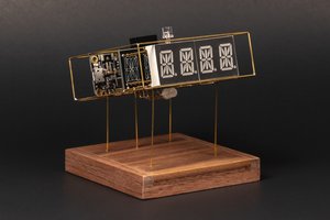
Hello guys, I made want to make a 7-segment display. But this time with bigger digits and RGB effects. Because this can be used to display some readings like Clock with Nodemcu, temperature monitoring using Arduino. Also, with an option of color changing after each second or next reading. I also have the similar one, which I designed a while back. That design has some Led orientation problems.
Because last time I used 2 LED’s to display per segment, our eye can’t regonize the digits too fast and accurate. Means we need a focus; I am happy with the design but now it’s time for update. JLCPCB is always with me to provide good PCB prototype and SMT assembly service solutions.

This mini led has voltage ratings: 3.0v to 5.5volts @16mA (for each Led). Our NodeMCU has 3.3-volt regulator, to drive all the LED’s properly.
LED WS2812B 3030:
I used ws2812 Neo pixel led, which comes with integrated ic so that we can address each segment separately. Not only the LEDs are addressable but also the color can be changed per pixel changing the digital value between 0-255(8-bit value).
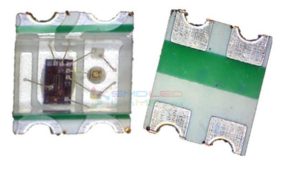
This led comes with 4 pins, the configuration of pins can be seen in the picture mentioned above. Also, these Led’s come with Data IN and Data OUT function, which make them more interesting and through this we can join them to show text or data.
Making 7 segment display using neo pixel led:
To make the panel, first we have to take a closer look on actual lcd. So that we can copy the arrangement of segments and design a code for that.
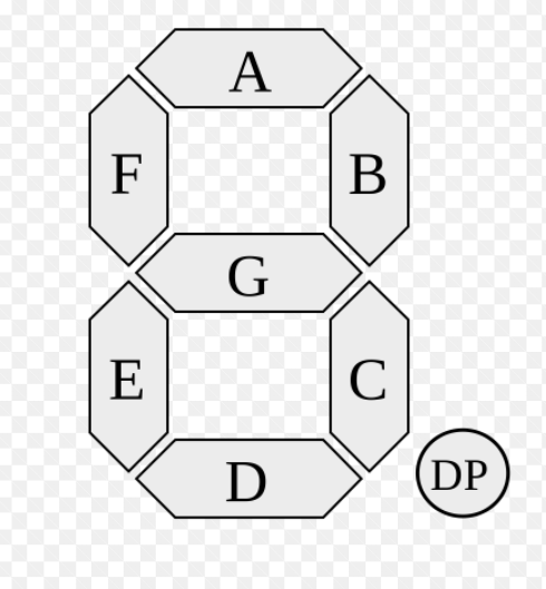
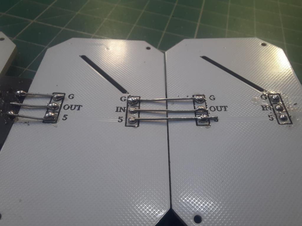
So here, segments are named as A, B, C…… to G, so to connect all the segments we use series data and parallel power method. All the power lines, GND and VCC are joined in parallel to all the led’s. Data OUT is supplied to Data IN of next Led in series. Always connect Dout of first panel to Din of second.
Dash connections:
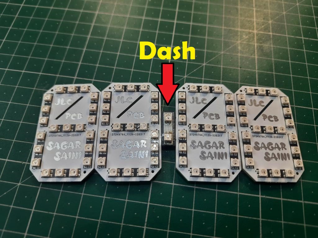
To connect the hours and minutes panel, A small PCB is there in between named as Dash, contains 2 LED’s as binary digits. These 2 LED’s glow after each second.

I used JLCPCB SMT assembly service for these good looking PCBs, here is the full review of the SMT assembly service. White color PCB, 1.6mm thickness and HASL finish is looking pretty damn good with JLCPCB SMT Assembly service. These Boards are fully assembled by JLCPCB, means all the components and soldering work is done by them. Why not to try this offer, JLCPCB SMT assembly service is staring from $8 and if you sign-up using this link, you will get free coupons of worth $30 and newcomer rewards.
Need of NodeMCU/ESP8266:

ESP8266 is integrated with a 32-bit Tensilica processor, standard digital peripheral interfaces. Our Esp8266 has on board Wi-Fi support, through this we can adjust the time over internet without any RTC(real time clock) module. This will reduce the connections and make this project simple.
If you are using my code, then there are 2 extra features you may add in this 7-segment clock.
1) Temperature and humidity using tactile switch.
Add a DHT11 sensor on pin number 13 and a tactile button on pin number 12 to get the temperature values on screen in Celcius or Farenheit.
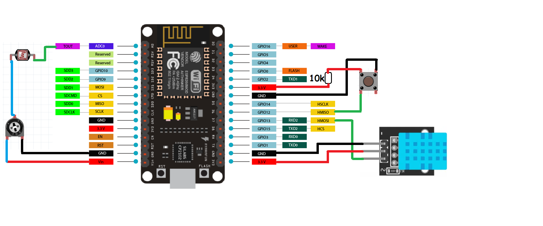
Connect the button pin 12 to 5volt using a 10k resistor and the other end to GND. Means when the button pin is pull down to GND, Display will show temperature readings. The code will also work without this Temperature sensor, so if you want to keep it simple there is no need of these connections.
2) Brightness control using LDR sensor at pin A0.
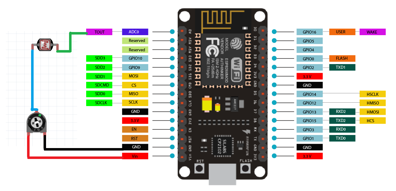
Add a LDR sensor with 10k resistor by making a resistor divider network on A0 pin, this will change the brightness accordingly. High brightness in day time, low in night. The code will also work without these sensors if you don't want adjustable brightness, it will locked on default settings.
7- Segment Clock:
I designed the circuit in EasyEDA for each segment here I am using 3 LED’s. So, a total of 21 led’s per panel is required to make this configuration. I made the connection pins at bottom layer...
Read more »
 romaindurocher
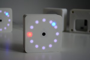
 mihai.cuciuc
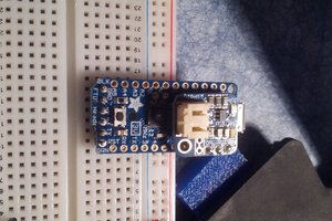
 Eric Friedrich