 deʃhipu
While I wait for the PCBs to arrive (they are apparently already on their way, and should be here next week), let's talk a little bit about how the communication with the display actually happens. I already mentioned that it uses 9-bit SPI protocol, and that means that each time a byte is sent to the display, it's prefixed by an additional bit that tells it whether it should be treated as data or as a command. But what are those commands and in what format is that data precisely?
We can learn all about that from the datasheet for the STE2007 chip (PDF) that is used in that display. For those who have already some experience with OLED displays, it's very similar to the popular SH1106 chip. In fact, in displayio we use the SH1106_ADDRESSING flag for it!
Let's start with the commands. Table 18 of the datasheet details all of them, but we will only need to use a few. Right after powering on, the display is inactive — we need to send it some initialization commands to make it work. Those commands are as follows:
E2 reset
2F power on
A4 display normal
AF display on
First, we do a software reset, just to make sure we get a clean slate. This is theoretically not necessary, but there could always be some glitches on the communication lines during power on, which could potentially send some random commands to the display, and it doesn't really cost us anything to be careful (we do a hardware reset with a pin anyways).
The next command switches on the internal power for the liquid crystal. The chip contains all the necessary circuits to provide just the right voltage for this particular liquid crystal panel, but it's off by default (because there is also the option of providing that voltage from outside), so to get anything displayed, we need to switch it on first.
Next, we switch the display into the "normal" mode, as opposed to "inverted", where all the pixels are negative, "all off", and "all on", which are used for testing. The normal mode is when a 1 in the chip's memory gets translated to a black pixel.
Finally, we send a command that actually makes the driver chip start sending the pixel data to the liquid crystal panel — this is separate from the power on, since if we provided external power, we would still want to do the display on command without doing the power on command.
After sending those four commands, the display will start showing the contents of the chip's memory — initially it's just random pixels.
Next, we will need to send the data to be saved in that memory, and for this we need to understand how that data is arranged. We can visualize it roughly like this:
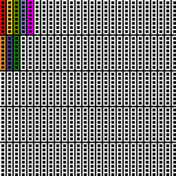
Since the display is monochrome, each pixel is represented by a single bit of memory. So a byte represents a set of eight pixels. In this case, it's a vertical line of eight pixels, as you can see on the image above — each of the colored "ladders" is one such set of eight pixels, or one byte in memory.
Furthermore, those bytes are arranged in what the datasheet calls "pages", and what we would probably call rows. Since the display is 96x68, we will have 9 rows of 96 bytes each (the last row is only partially visible). We select the row with the "page address set" command, which is actually 16 different commands, one for each page (there is a bit of redundancy there), from B0 to BF. The chip actually has more memory than fits the screen, and that can be used for vertical scrolling using the "start line address set" command 40-7F, but we are not using it in this case.
Each time we send a byte of data, it's getting saved to the current page, and then the "cursor" is advanced by one horizontal position. This means we can simply just stream 96 bytes for a row. Then we need to switch to the next page, and stream the next 96 bytes. If we didn't need to update the whole width of the display, though, we can also move the cursor horizontally using the "column address set" commands — there are two sets, 10-17 for the top three bits of the address, and 00-0F for the lower 4 bits. That gives us addresses of up to 127 — again, the chip has some redundancy.
And that's it. That's all the commands we need. You can see that it's very convenient for us to use 8-pixel high blocks for the PewPew "pixels", because they just fit in the pages that way. If we picked any other size, we would need to combine data from two rows for every byte that is sent to the page, which is not much more work, but can get a bit annoying. This way for each large block we just send one of those strings, depending of which "color" we want:
b'\x00\x00\x00\x00\x00\x00\x00\x00\x00\x00',
b'\x44\x11\x44\x11\x44\x11\x44\x11\x44\x11',
b'\x55\xaa\x55\xaa\x55\xaa\x55\xaa\x55\xaa',
b'\xff\xff\xff\xff\xff\xff\xff\xff\xff\xff',
And that's it. That's all we need to know about this display.
Discussions
Become a Hackaday.io Member
Create an account to leave a comment. Already have an account? Log In.