 ogdento
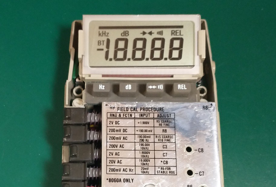
Coming around to designing a custom LCD for the Fluke 8060a took a few failed starts.
Years ago I saw a post on ModemHead's awesome blog where a user named Dmitri built a custom LED-based display for his 8060. I thought this was extremely cool so I reached out to ModemHead and he put me in contact with Dmitri who told me more about his display. I struggled with cutting a test template on a crude drill press "mill" and ultimately tabled the idea while I explored fitting the 8060 with an OLED instead. That was a non-starter because of the hardware required to convert the LCD drive signals to data for the OLED, and that it would have to fit and operate in a battery powered meter that doesn't have a lot of extra interior space.
Then one day while scrolling through Hackaday I saw a charlieplexed display by Bobricius, where he used the fabricator to cut segments into a pcb! That gave me the idea to merge Dmitri's display concept with Bobricius's build technique... My new plan was to build a display using 2 layers of pcb and some translucent epoxy. The top pcb would be routed out in the shapes of the digits and other indicators I needed, and would be attached to the lower pcb which would mate with the multimeter's existing LCD pads on one side and host 40-something tiny LEDs on the other. The slots would be filled with the epoxy to diffuse the LEDs, and the whole assembly installed into the existing display carrier.
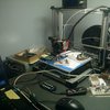
I started a prototype before getting any boards manufactured, but the tiny LEDs were too fiddly for me to work with and I realized I didn't have enough time, patience, or skill to build them. I had 4 meters left that needed new displays and without any real smd tools (stencils, reflow oven, pick and place etc) the work would have been extremely tedious... so I tabled that idea too.
Some time later I stumbled across an eevblog video series Dave did on making custom LCDs, and I figured what the heck - why not give it a shot? This project is the result of that effort.


 Valrum
 deʃhipu
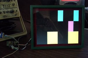
 Eric Hertz
 Gregory Sanders
I had issue of LCD blackening, long back, it's the glue on the polarizer, at the back of LCD which hardens (humidity plays a big role in it). I removed the polarizer with thin aluminum foil on it and replaced with another non-sticking polarizer and aluminum foil (mounting
them is a bit tricky). Replaced the front polarizer too.
If the LCD is not broken and u need to reuse it then cleaning the stuck glue is not as easy job. It took me about 1 hr to do so with isopropyl alcohol.