As many of us, we developed projects with the Raspberry Pi, and installed them to our customers. It was great to have such a thing as the Raspberry Pi's, but these also have problems:
- The SD-card as the main storage, where also log files are continuously stored, broke regular after some time. And a broken SD-card in a Pi means system down. Even high-end SD-cards last longer, but finally also broke. A system for 24/7 usage, simply can not solely base on an SDcard. These is a fundamental design mistake for a 24/7 system, what we learned the hard way.
- not enough UARTs, so often USB-to-UART adapter had to be used. Looks unprofessional in a device you like to sell, and brought additional stability problems.
- Finally sourcing problems in the chip crisis. If today be lucky to buy a Pi, then for a much higher price then before. We need a reliable, predictable source to not disappoint our customers.
We needed a robust system, wired Ethernet, be immune against a broken SDcard, and the possibility to add functionality to the system depend on the project. We did not need the high processing power of the Quad core GHz processor in the Pi, just enough processing power to read and write to a PostgreSQL database, read HF, UHF and/or QR-code, and switch some relays. Stability and robustness was more important then processing power. So we designed and build our replacement for the before used Raspberry Pi's: the EsPiFF.
The current version of our prototype contain 2 I2C IOexpander to serve the 40 pin Raspberry Pi header. This is ok for our current projects, but we wanted a new revision with a much faster solution, so we came up with the RP2040 as "Pi Header CoProcessor". It will also bring an USB host, what further expand the possibilities of these board.
We also have the SD-card socket placed wrong in the prototype. All other functionality is working so far: We have wired Ethernet and Wifi, can read and write from the SD-card, can use 3 UART at the same time (we often need a HF and UHF RFID reader, connected by UART, and a Nextion HMI). The 15 pol connector next to the USB is to connect a Chafon UHF RFID reader. The 2 switches next to the Chafon connector are to switch the UART0 from the ESP32 to ether the USB-to-UART or to the UART connector. labled HF on the prototype.
We used a USB-C as the debug connector, and it can consume up to 5V/3A from the PSU or Laptop. That is a big improve over the 5V/100mA, what you usually get from Micro-USB connectors. It is still USB2, but over the USB-C connector. This enables us to consume up to 15W, important when you have power hungy HATs.
We are working now on the Rev. B of the EsPiFF. Schematics are nearly finished, will start the layout soon. We will made the following changes:
- replace the 2 I2C IOexpander with a RP2040,
- place a USB-A connector next the RJ45 connector (the RP2040 can be a USB host!)
- fix the SD-card placement,
- change the value of a resistor on the LAN8720,
- remove the blue terminal connector on the bottom right. Its purpose was to have an optional power-in connector, but we see no real need for it. And we need the space.
- change the ESP32-WROVER-B to ESP32-WROVER-I to have an additional IPEX connector for an external Wifi antenna.
Finally, we plan to run a campaign on Crowd Supply. Stay tuned for updates.
Update: the final version, what will be offered at Crowd supply, is the version 3.1. We did the following changes:
- Replace the Ethernet PHY LAN8720 with a IP101. The LAN8720 showed stability problems in combination with the ESP32-WROVER module, and several other ESP32 projects with wired Ethernet (like Olimex, wESP), had done the same: replace the LAN8720.
- Added the PoE header, to enable the option to power the EsPiFF by the PoE-HAT.
- Added a 6 pin connector for our upcoming TFT modules.
- the 2 DF11-8pin connectors with the UART signals are on the place where the RasPi 4 place the micro-HDMI connectors. Existing enclosures for the RasPi 4 allow connecting...
Read more »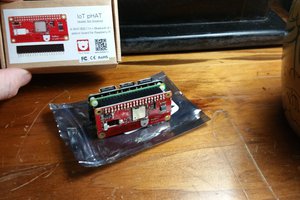
 Thomas
 ajlitt
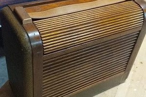
 Jacob Daniels
 sfdogecoin