Lattice60 uses hand-wired switches and a Sparkfun Pro Micro running QMK.
All files will be uploaded here and to the Github repository on the left side.
Custom Ortholinear 60-ish Percent Mechanical Keyboard
Already have an account? Log in.
To make the experience fit your profile, pick a username and tell us what interests you.
Lattice60 uses hand-wired switches and a Sparkfun Pro Micro running QMK.
All files will be uploaded here and to the Github repository on the left side.
Plate.3mfFinal keyboard plate.3mf - 265.31 kB - 02/20/2023 at 01:25 |
|
|
Case.3mfFinal keyboard case.3mf - 450.09 kB - 02/20/2023 at 01:24 |
|
|
stringing.3mfModel to test stringing on 3D printer.3mf - 30.31 kB - 05/30/2022 at 13:29 |
|
The layout and key functions of this keyboard have evolved substantially since its initial use. Since I run the QMK firmware on the Pro Micro, I have fine-grained control over the behaviour of every key. The changes I made over time, aimed to reduce finger movement and increase typing comfort – to a point where some of the keys of the board remain used altogether (those keys would be eliminated in a v2 of the Lattice keyboard). I expect more changes to the firmware to be pushed to my Github repo in the future.
The current firmware compiles with QMK v0.17.
I went with Colemak-DH as the base layout and incorporated the NEO layer 3 for symbols, similar to what has been done by Jan Lunge. Just like him, I also added one layer for navigation and numbers. Then I made the following modifications for a more seamless interaction between the layers:
QMK gives many options to reduce the travel distance of the fingers. The keys I found most straining were the far-away ones which I had to reach with my right pinkie. Here are my attempts to keep by fingers as close to their natural position as possible:
The behaviour and timing of QMK keystrokes has been adjusted precisely. A caveat of overloading keys with so many functions is that an unintended action might be triggered. The following adjustments reduce the chance of that happening:
I had the choice between designing a custom PCB or sit down and handwire every switch and connect them to the microcontroller board. I decided for the latter, even though that meant soldering for hours on end. And, as it turned out later, my mediocre soldering skills lead to some reliability issues.
Still, I think handwiring was the best option for a first prototype. Below I describe my process which makes it look tidy and organised. The QMK documentation gives a great first introduction into handwiring. It also compares a bunch of different approaches, of which I chose to follow the one by cribbit. In that case, diodes are wired column-to-row, and attached to the row wires of the matrix. The column wires are soldered to the switches directly. Then the MCU board is connected. This blog post by Dave is interesting as well.
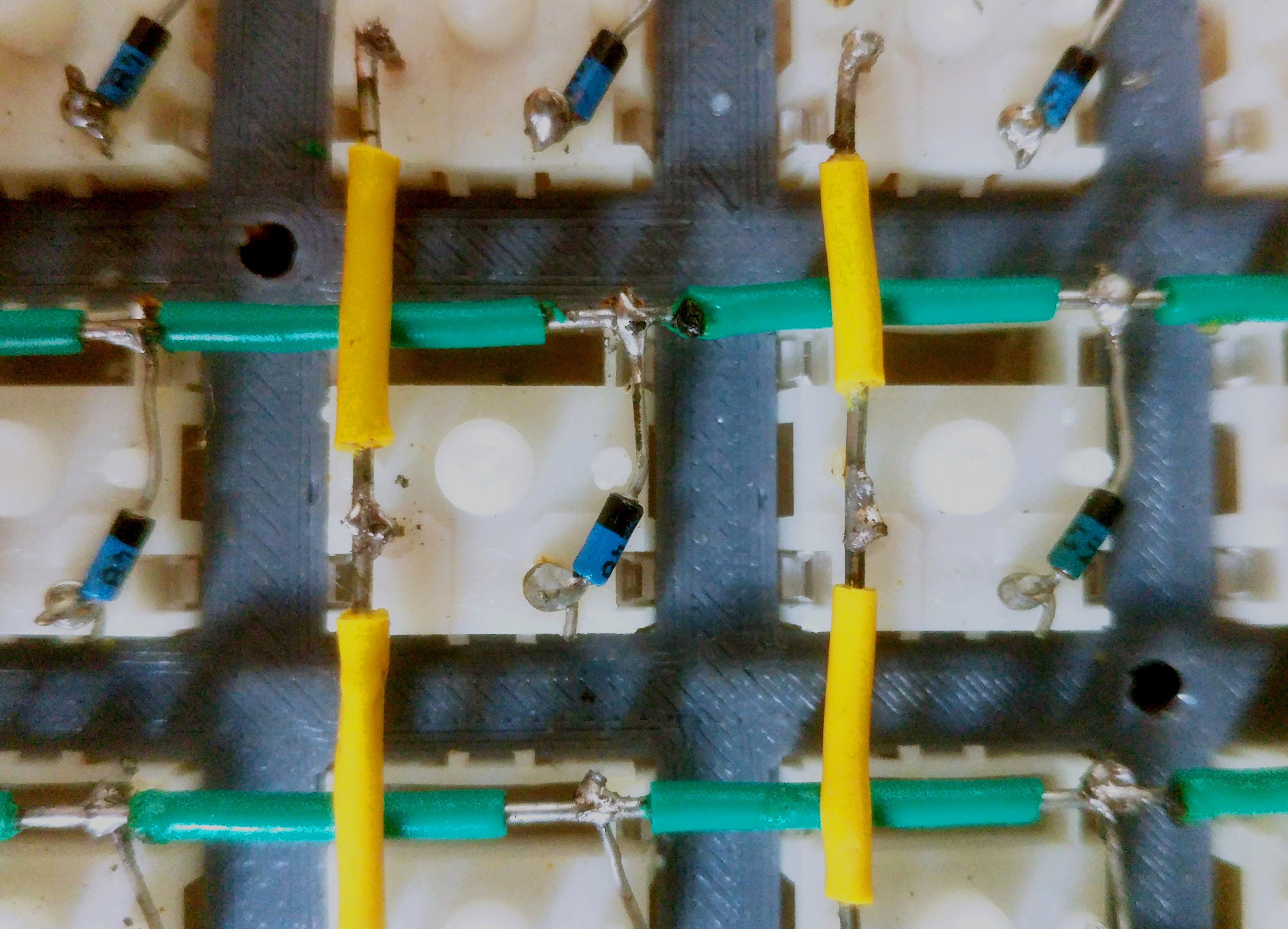
First, a loop is made in the cathode lead of the 1N4148 diode, places onto the pin of the switch and tightened, then soldered. I regret not making a loop on the opposite anode end of the diode. It resulted in me having to re-solder the joints of a couple of switches later on. For the switch matrix, I used 20 AWG solid core wire which is rigid and easy to bend. I cut around the insulation and pushed it along the wire to expose only the part of the wire where the joint was located. After that, it looked like this:
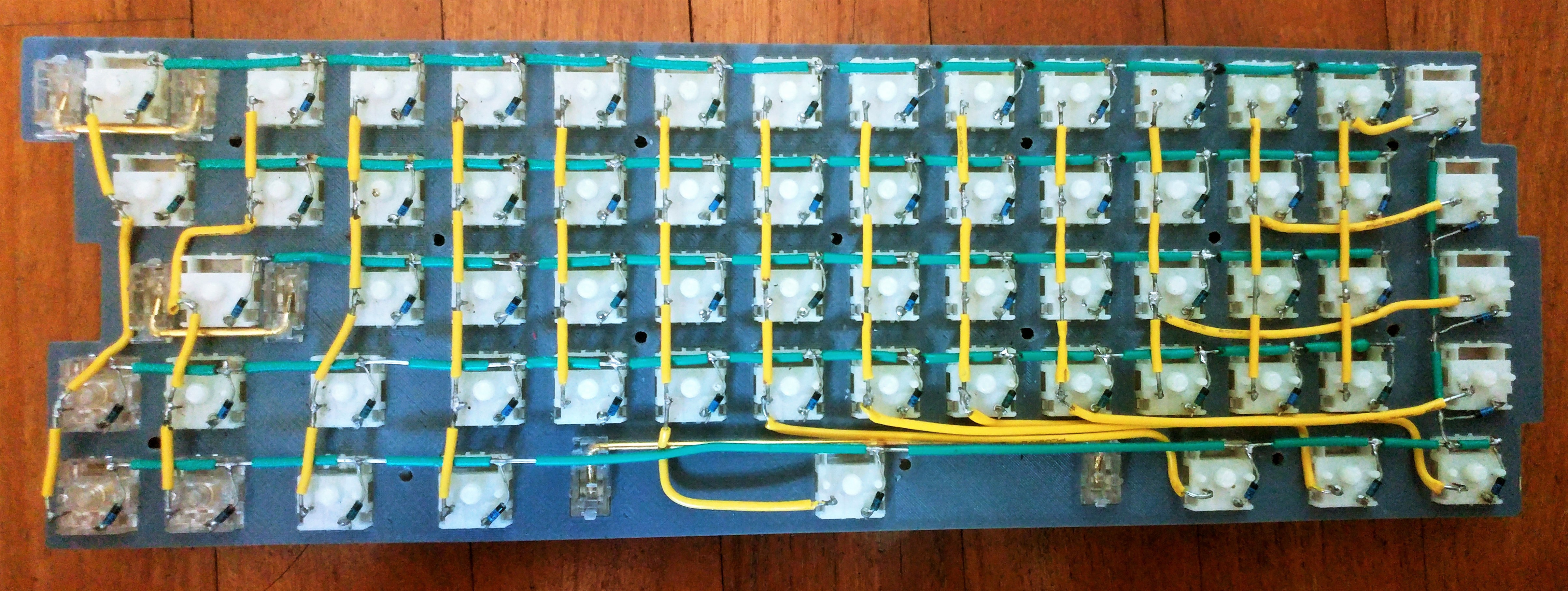
I need to admit a bit of a miscalculation. The ProMicro board has 18 usable inputs. However, I have designed my layout to be 14x5, which would require 19 pins. I worked around it by wiring the last matrix column as part of the bottom row as seen in the picture below. While that works perfectly fine, you'd be better off getting a board with at least 19 inputs (such as the Teensy 2.0).
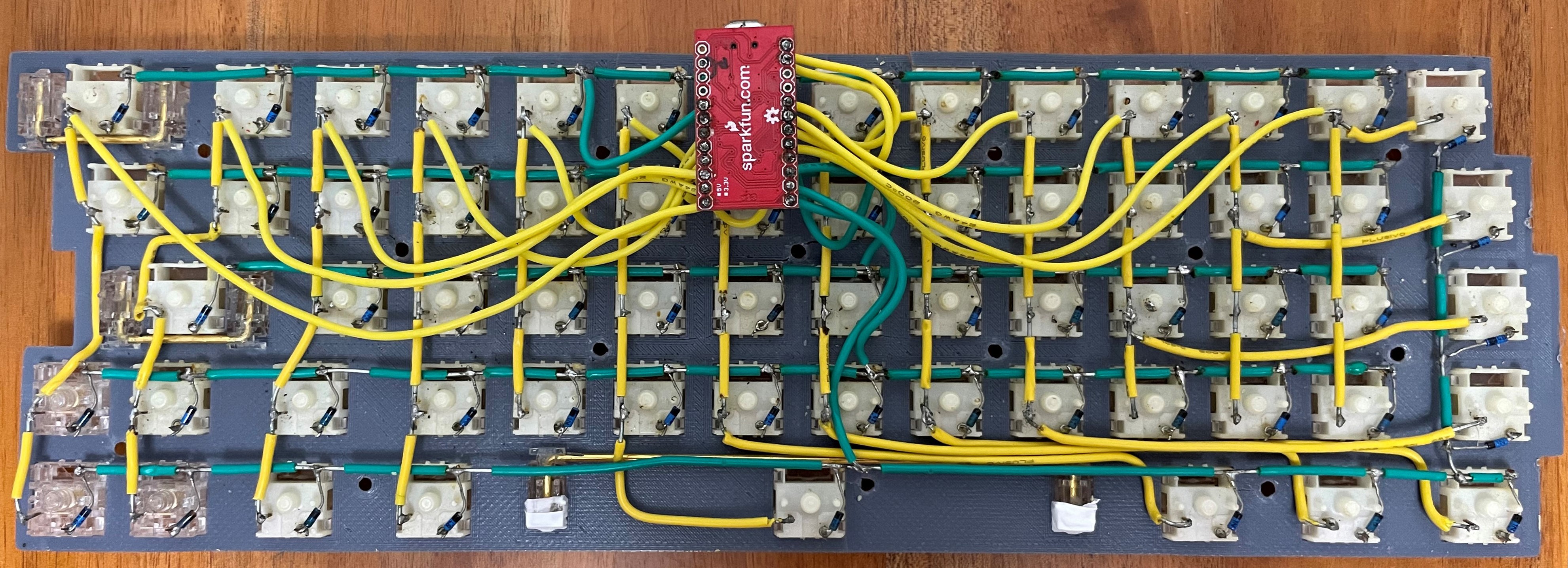
The position of the MCU board is – as determined by the case design – in the middle of the upper edge. To connect the board to the rows and columns, I used 24 AWG stranded wire. It is very flexible which helps with the assembly. All pins of the ProMicro can be used except GND, VCC, RST and RAW.
It does not matter where on the row or column the wire is soldered to because it is all connected anyways. Choose the wire lengths so the MCU board can still be lifted from the plate by around 1 cm. If it is shorter, the assembly will be difficult. But too long and it will be tough to accomodate all the wiring in the tight spaces of the case.
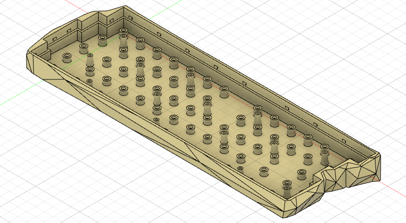
Low-poly design is a style which can be applied to three-dimensional models. It intentionally reduces the number of polygons, which make up the mesh of the model. Because that obfuscates some details, it is kind of a minimalistic style – and I love it. So I wanted to apply it to my keyboard case.
But simply taking my case from Fusion 360 (which is essentially a box), converting is to a mesh and reducing the number of polygons wasn't going to work. Because all the corners and edges would just disappear. Below I describe my steps to a successful low-poly design using Fusion 360 and Blender.
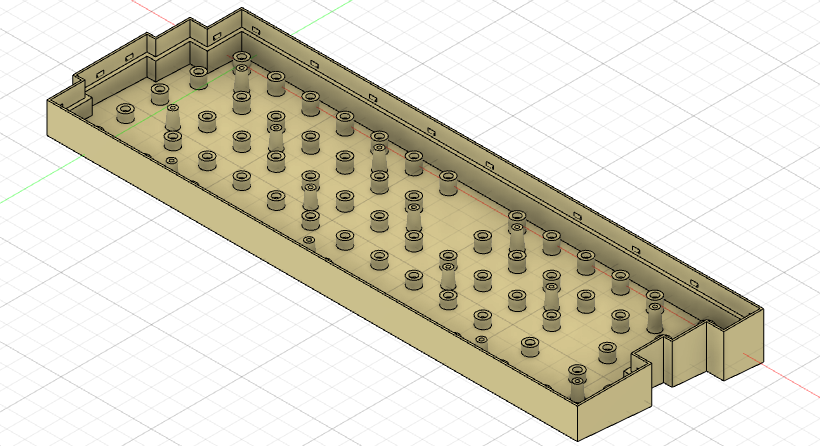
Based on my keyboard plate, I created a basic case. This already includes an angle of inclination of 5 degrees.
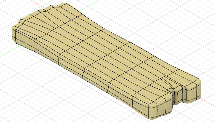
In Fusion 360, I created a new Form and, to start off, inserted a box which roughly enclosed the existing case body. The form should reflect a certain number of details of the basic case, such as the stepped edges on the left and right side. I inserted additional edges and pulled them around using the Modify tool until I got something like this:
You can see that I thickened the form on either end to ensure that there are still some edges left after I applied the low-poly style. I also introduced some irregularities along the long sides of the case. That is because I wanted the low-poly pattern on the front and back side as well. Without those dips and humps, the side would have just be flattened to a single polygon.
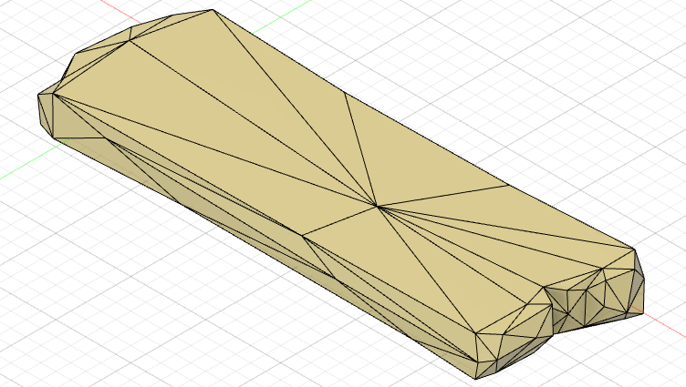
In Fusion's Mesh tab, the Tessellate command converts a regular body into a mesh. I then ran the Reduce command with the following parameters.
The result was very much to my liking. However, there was one corner that was cut off too much. meaning that there would not have been a continuous upper edge on the case. Getting those fine details right in Fusion 360 is hard, because you never know how the reduced mesh will look like when making modifications to the initial form from Step 2. Believe me – I dragged the points and edges all over the place without success.
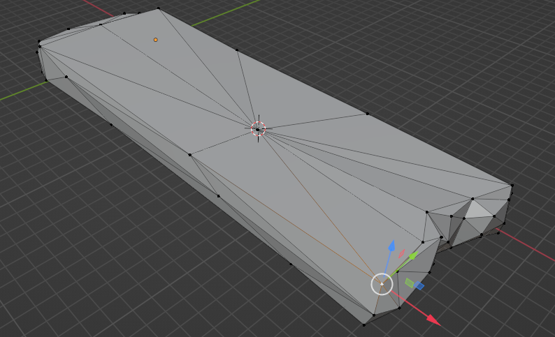
Instead of hoping that changes to the form lead to an improvement in the reduced mesh, I decided to work directly on the reduced mesh and make the changes there. Blender was, weirdly enough, the only tool I found which allow individual mesh vertices to be repositioned. I used the STL file format to transfer the mesh from Fusion 360 to Blender and back.
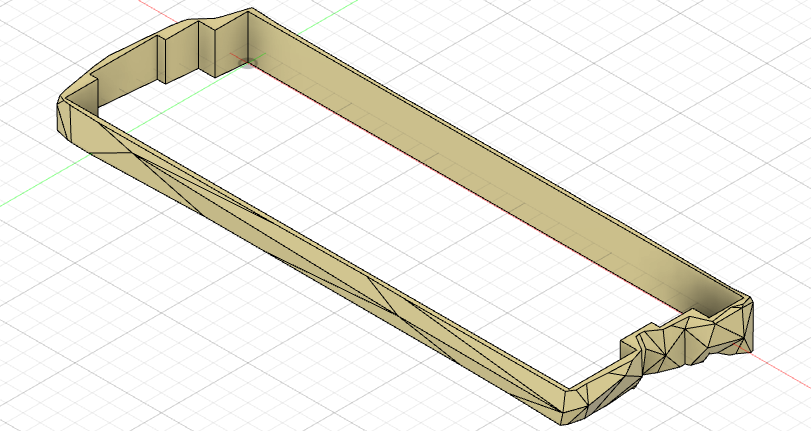
In Fusion 360, I used the Insert Mesh command to import the edited mesh. Some iterations were needed between this step and the next ones to get it right.
To replace the four sides of the original case from Step 1 with the new design, I first converted the mesh to a solid body. Then I applied the following operations:
Finally, I joined the low-poly body with the original case using the Combine Tool.
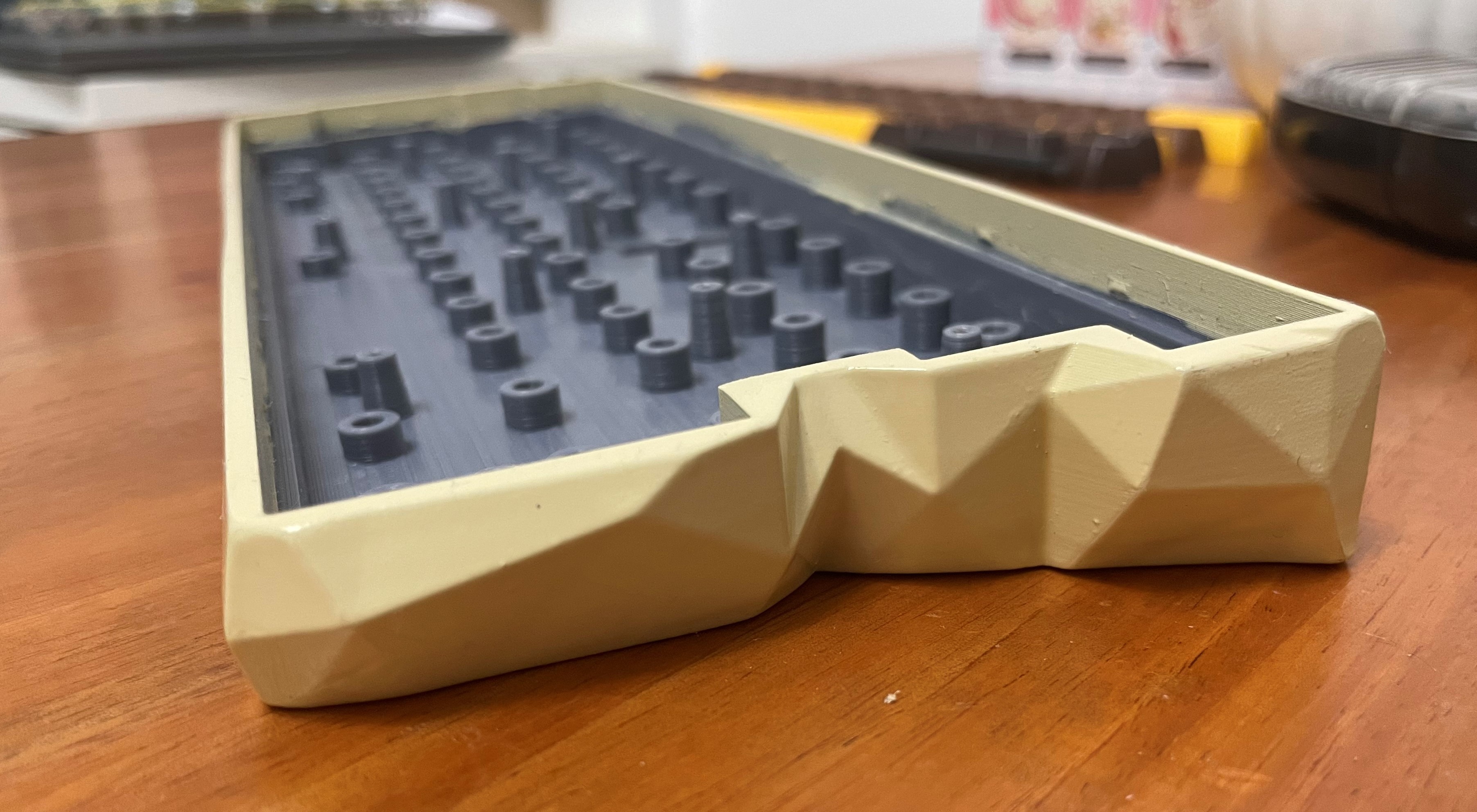
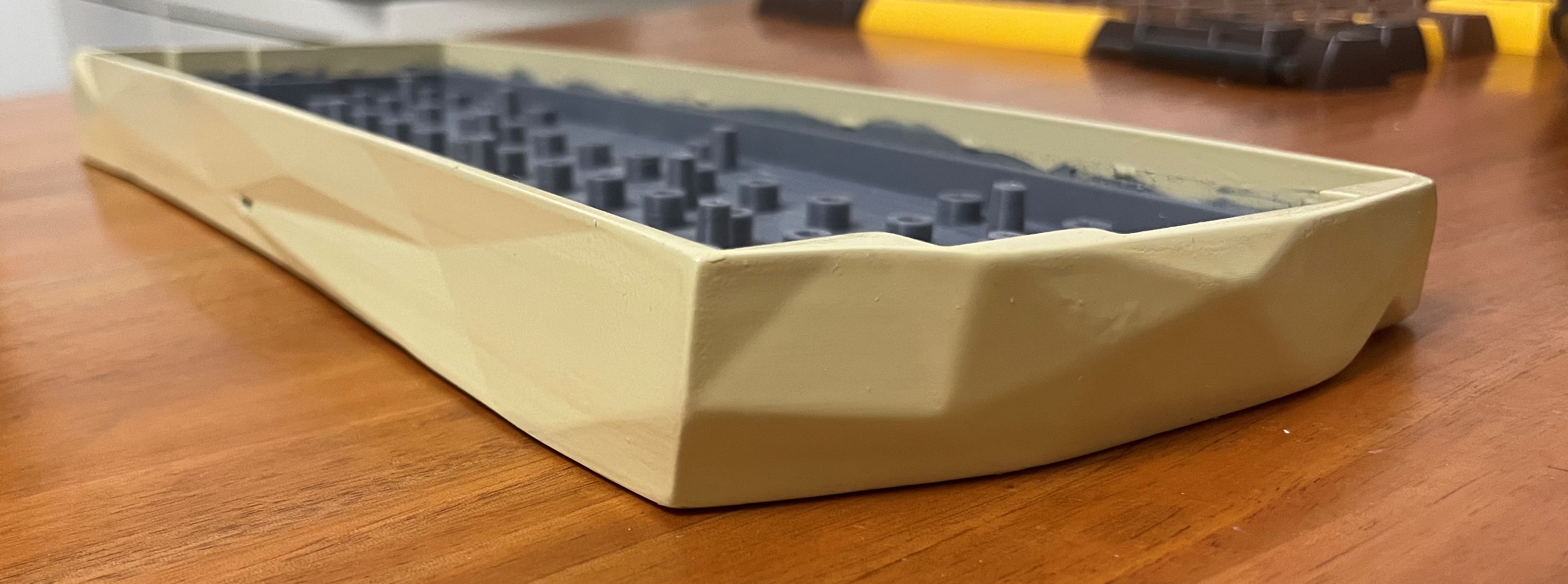
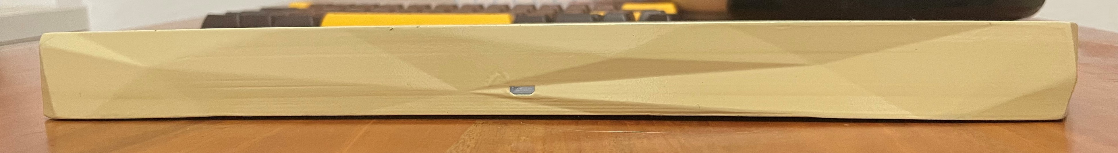
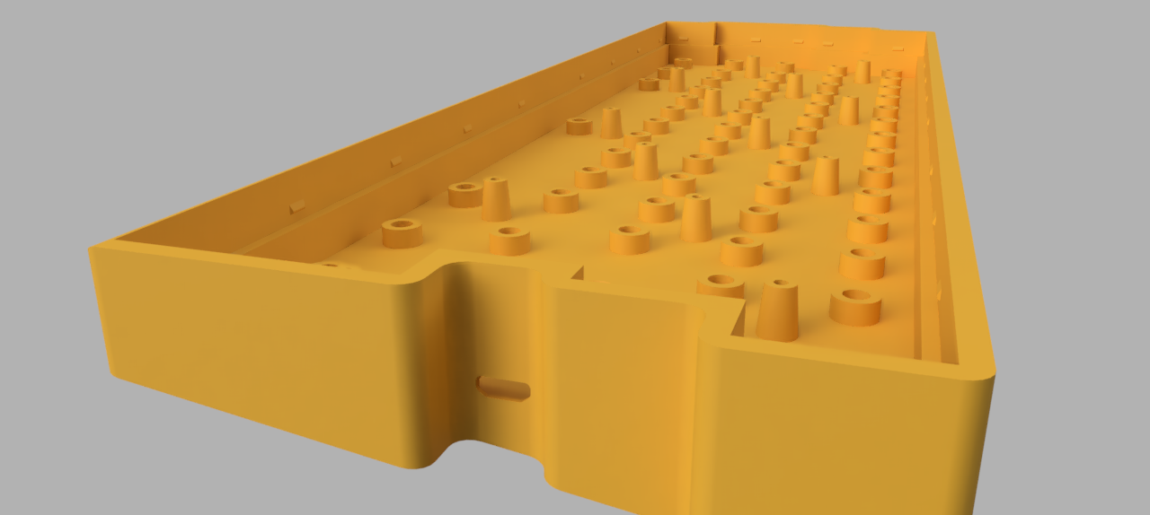
I uploaded the final case to this project for you to print. It can also be found in the Github repository along with the firmware files. Here are some pictures of the final result:
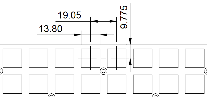
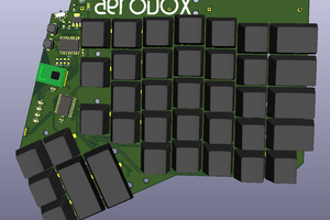
The positioning of keycaps and switches on the plate follow the keyboard unit u, which is usually 19.05 mm. Your letter and number keys have a width of 1u, while others use multiples of that (1.25u, 1.5u, 2u, ...). Since this unit is so ubiquitous in keyboard plate design, I saw it as a perfect opportunity to set it as a user parameter in Fusion 360.
The final model files for both plate and case can be found under the project files or in my Github repository. Here are some pictures of the prints:
The spacing between keys is simply 1u if both keys have a width of 1u. In the general case, the equation below calculates the distance between two keys, with the widths being multiples a and b of u. I included an example for a = 1.5 and b = 1.25. Since I already had u stored as a parameter, Fusion 360 calculated the exact value for me.
Armed with a caliper, I set out to get the dimensions of the switch sockets for the perfect fit. That was easier said than done, because a bit too loose and the switch would come out easily, slightly too tight and plate would bend after fitting all the switches. A hole size of 13.8 mm gave the best result.
Around the edge of the plate I added a margin 0.5 mm to the usual u-spacing. This also determined the space between key caps and case. But I then had to offset the edge around the plate inwards by 0.25 mm for better assembly, resulting in the 9.775 mm as shown in the drawing below. The thickness of the plate is 1.5 mm.
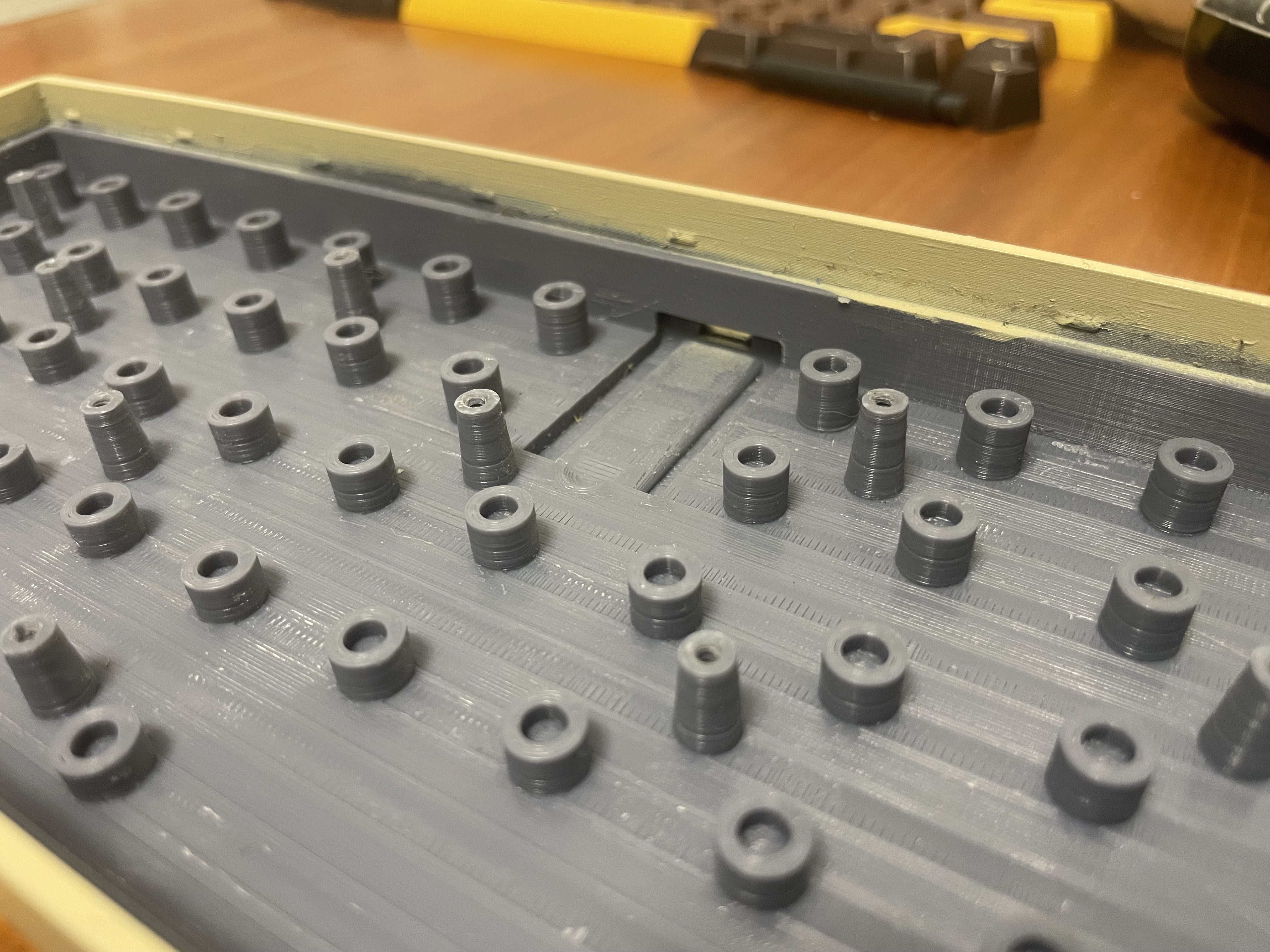
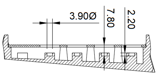
Having switches suspended by a thin sheet of printed plastic made the keys flex with every stroke. To prevent that and give the keyboard more stability in general, each switch has a socket it sits in. That is a hole with a diameter of 3.9 mm and a depth of 2.2 mm, which receives the thick cylindrical pin on the bottom side of the switch. The distance between the top of the plate and the bottom of the socket is 7.8 mm. That is shown in the following cross section of the case and plate.
Stabilisers are mounted onto the plate from below. The plate has a cut-out as shown in the drawing below. The stab wire is under the the narrow side of the cut-out.
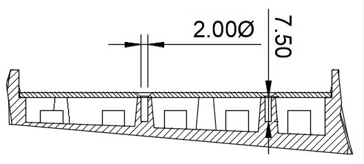
The plate sits on a 2 mm wide ledge along the inner edge of the case and is held in place by bumps protruding from the side. In the middle, there are numerous self-tapping screws of gauge 2 and with a length of 3/8" (= 9.5 mm). A hole diameter of 2 mm gave the screw a good grip, while not splitting the plastic. The hole is 7.5 mm deep.
The plate of the keyboard is printed flat on the print bed. And because of its size, I have to position it diagonally within my 300×300 mm print area. While I never had problems with bed levelling when printing smaller parts, this one turned out to be quite a challenge. It made me check printer settings I've never thought of before.
The initial assembly of the printer mainly involved mounting the gantry to the base frame. But since test prints at that time looked fine, I didn't pay much more attention to the assembly accuracy.
The fine-tuning for the plate print started with the levelling of the X-axis. I followed Method 1 of the official service tutorial. But before tightening the eccentric nuts along the vertical tracks, I also ensured that the two Z-axes run in parallel. After measuring the distance between the two vertical gantry posts near the top, I brought the extruder to its maximum height. The same distance was then set near the bottom, before bolting it down to the base frame again. Contrary to the Creality troubleshooting tutorial (part 1), I tightened the eccentric nuts quite firmly, so they can barely be turned by hand. The same goes for the eccentric nuts on the X-axis, since the auto bed levelling relies on all axes being rigid.
For the Y-axis, I roughly followed a video and first loosened the middle pulleys under the print bed on both sides. The two outer nuts on the right side should then be tightened to remove any play of the print bed. Ensure that there is no wiggle over the whole range of motion of the Y-axis. After that, I tightened the middle pulleys on both sides to the same degree as the other four, so each of them touches the rails at all times. Lastly, I also tried to straighten out the rails by loosening the middle bolts as suggested in the video. But since my extrusions don't seem to actually be straight, I had to forcefully bent them outwards and holt them in place using the bolts in the middle.
After successfully levelling the print bed, I faced another problem. While printing the first layer, ripples formed as if the extruded filament is pushed around by the nozzle.
A helpful forum post confirmed my suspicion that the nozzle is too close to the print bed. The problem was resolved by increasing the Initial Layer Height and therefore the clearance of the nozzle. I didn't make any changes to this parameter.
The post also mentioned the friction of the levelling card, which corresponds to the Z-Axis Compensation on the printer. That is a fixed offset for the nozzle height. The dilemma: increasing it will get rid of the ripples, but might lead to bad adhesion of the filament to the bed. The best solution for me is to
Applying glue stick to the print area helped to hold the first extrusion lines in place. In the slicer, the Printing Temperature Initial Layer can also be increased by 5 deg for better adhesion.
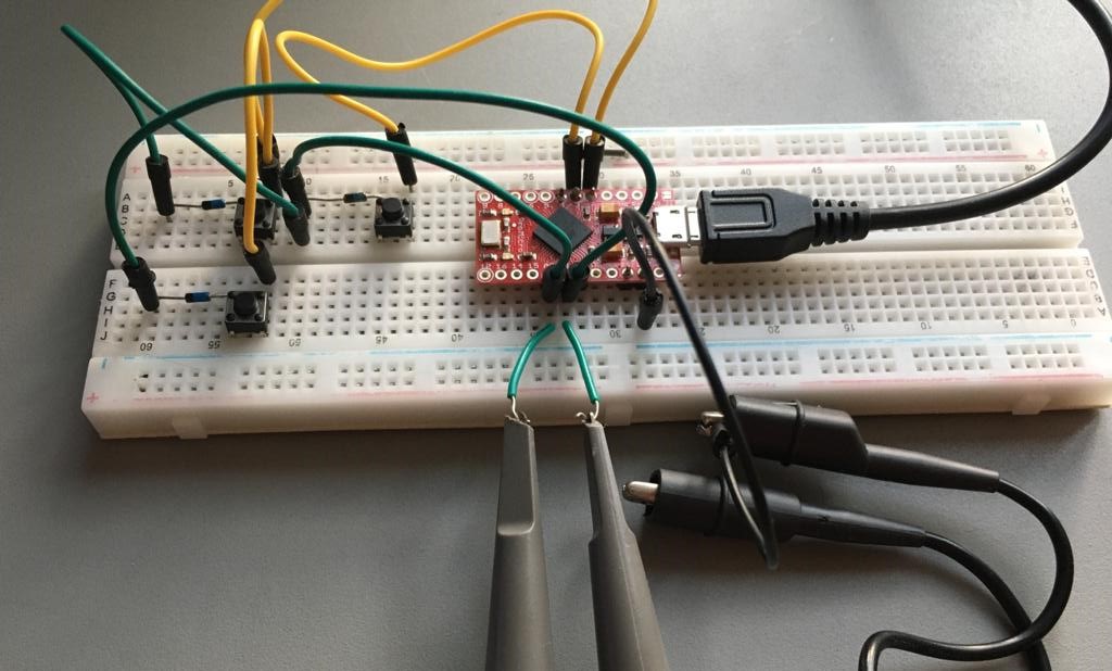
In a previous log I have setup a breadboard with a Pro Micro and some diodes and switches to test the firmware. I was interested how the microcontroller (MCU) actually finds out if a switch is pressed and at what speed it does that. Recall that the keys are arranged in a matrix, where switches of each row and column are connected to one another. Each row and column also get assigned a pin on the MCU.
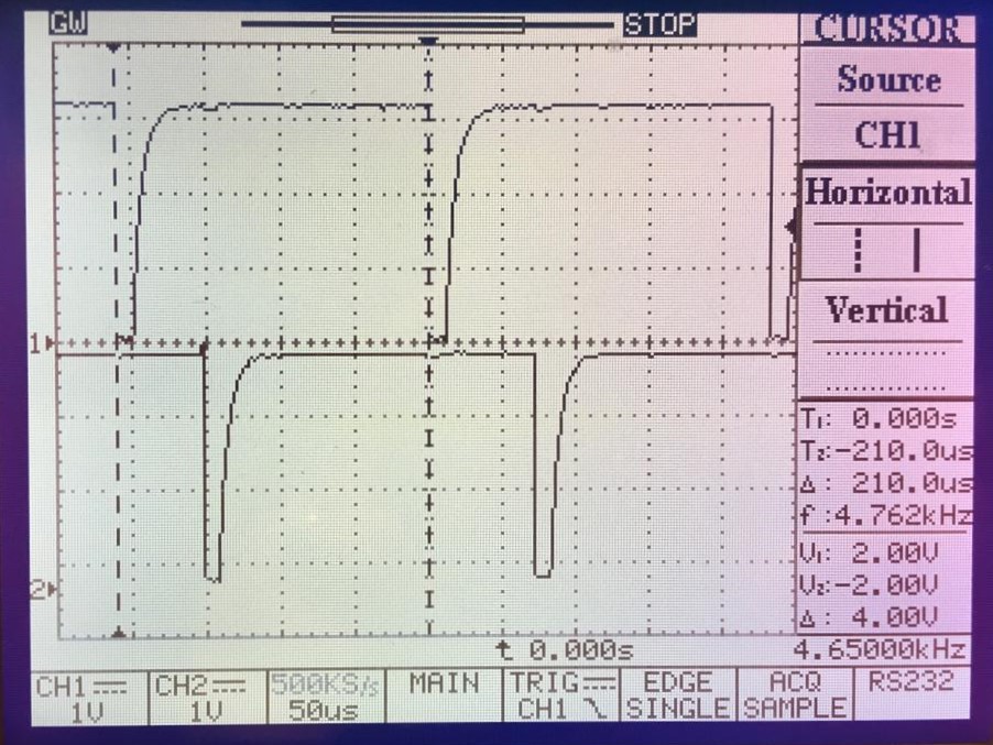
Due to the limited number of connections to the MCU, not all switches can be read at once. Instead, matrix scanning is applied. In the case of QMK, rows are read in a time-multiplexed manner, one at a time. This can be visualized by hooking up the two channels of an oscilloscope to the two rows of my 2x2 test keyboard (green cables).
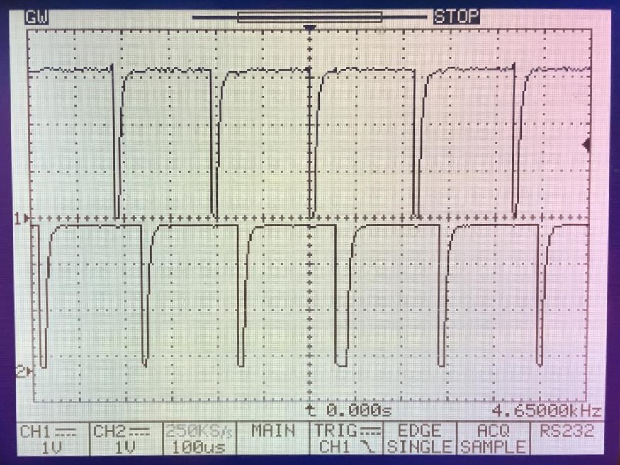
The image below shows the signal captured by the scope. The upper plot belongs to row 1 and the lower one to row 2. We can observe that the signal is high by default. The pulses, which occur at a fixed rate, indicate that the respective row is being read.
The row pins are outputs of the MCU, since the pulses are present regardless of the switches being pressed or not. Accordingly, the column pins are configured as inputs. They are connected to an MCU-internal pull-up resistor. That means their input signal is high by default, except if the line is pulled to ground. And that only happens if the following two conditions are true:
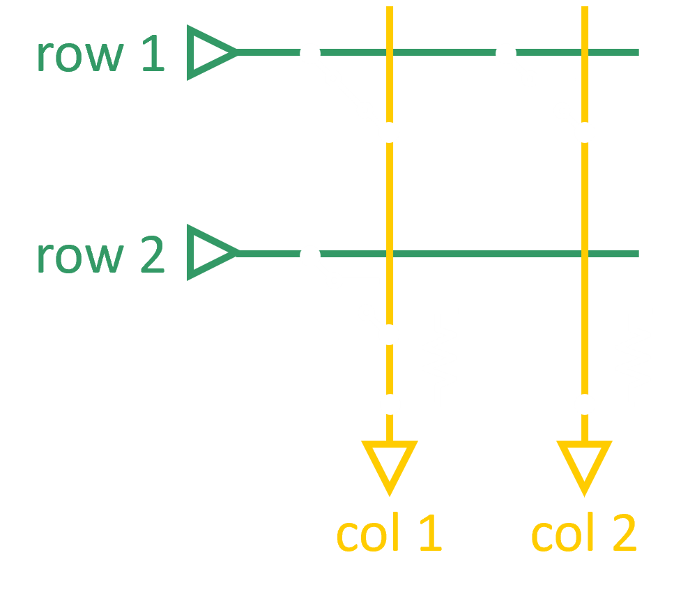
A schematic of the 2x2 keyboard should make that clearer. In the below example, switch (1,1) is pressed. When row 1 is scanned (by pulling the line to zero), the inputs read 0 and 1 for the two columns, respectively. For row 2, both inputs are pulled high by the resistor since no switches are pressed. This way, the controller can work out the coordinates of the pressed switches.
But how fast is this whole procedure? Using the cursors on the oscilloscope, we can determine the time difference between subsequent pulses on a row. You can see that keys are read every 210 us or more than 4000x per second. Pretty fast! So, it's unlikely that keyboard will ever miss a keystroke. The overall latency until the input is recognized by your computer is obviously much longer since it needs to be processed by the Pro Micro and the computer hardware first.
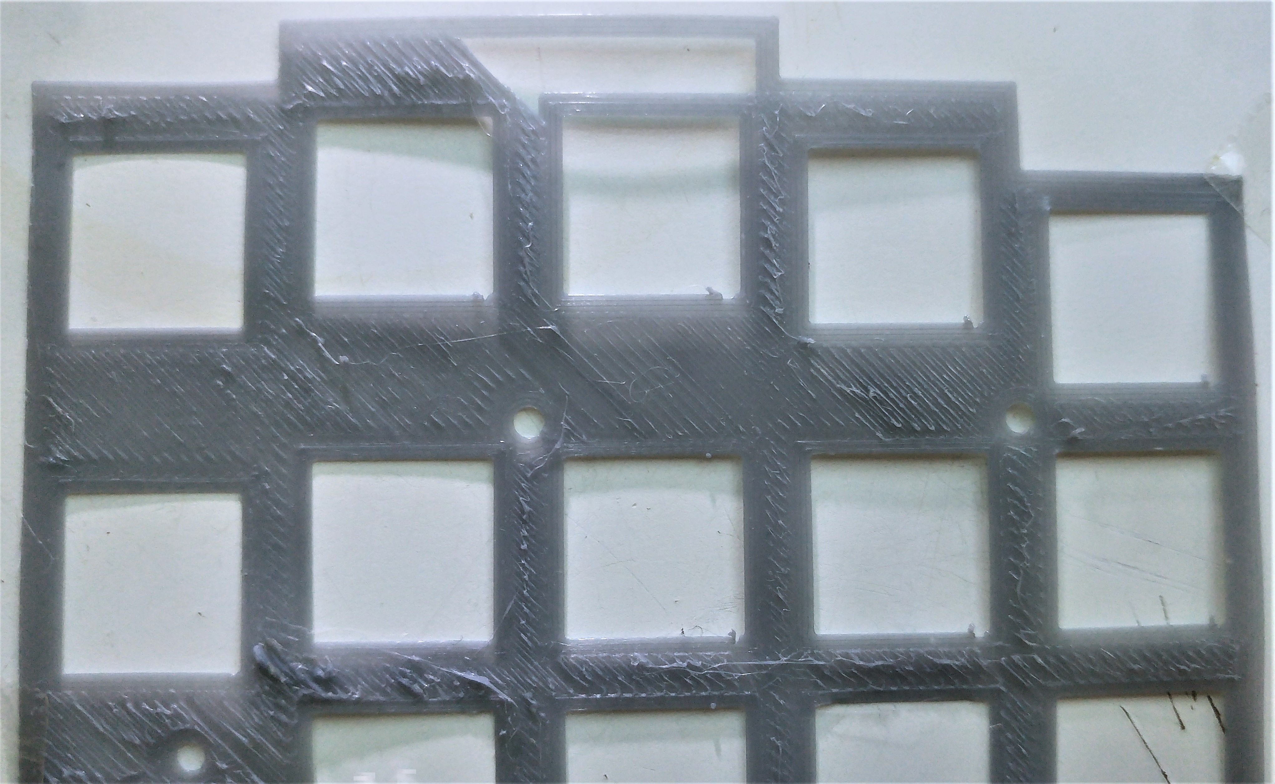
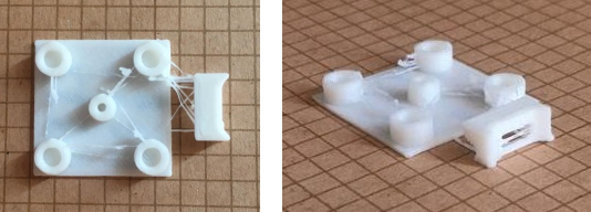
In order to stabilize and prevent switches from moving when being pressed, each of them sits in a socket. And mounting of the keyboard plate requires studs which hold the screws. While 3D printing, the nozzle travels between all those protrusions at every layer. That sort of geometry frequently causes stringing, where material oozes out from nozzle, when it shouldn't: during travel moves. Same goes for the USB connector, where stringing appeared in the hole.
EDIT: Stringing is highly dependent on the quality of your filament. Below tests were conducted using Creality's PLA which came with the printer. Presumably, the filament also contained moisture at the time of printing. I ended up printing the case with eSun PLA+ and smaller Retraction Distance/Speed as recommended by eSun. I also disabled Combing completely to reduce print time. Almost no stringing occurred. Refer to below table for the final values.
I use the Creality Slicer, which is a fork of Cura. To optimize the printer settings, I have created a small test setup, which completes printing in around 15 minutes. You can see that the original print settings are pretty bad:
| Parameter | Default Value | Creality PLA | eSun PLA+ |
|---|---|---|---|
| Retraction Distance | 5 mm | 10 mm | 4 mm |
| Retraction Speed | 60 mm/s | ← | 50 mm/s |
| Combing Mode | Not in Skin | ← | Off |
| Outer Wall Wipe Distance | 0.0 mm | 0.5 mm | ← |
| Travel Speed | 120 mm/s | 200 mm/s | ← |
The first thing to adjust were the retraction settings. Before every travel move, the filament is pulled back by the extruder to relieve the pressure in the hot-end and prevent it from oozing. The default Retraction Distance was set to only 5 mm. Increasing that to 10 mm made a big difference. I have also experimented with different Retraction Speed, but the effect was not visible in the test prints, so I just used the default.
I left the Combing Mode set at the default "Not in Skin", which adjusts the travel paths such that the nozzle moves over already printed objects as much as possible. This way, the leaking material is spread across the printed surfaces instead of building strings.
Another setting to adjust was the Outer Wall Wipe Distance. Before each travel, the nozzle loops over the just printed geometry to "wipe off" the excess material. From my experiments, the impact is almost negligible. My final setting is 0.5 mm.
Increasing the Travel Speed minimizes the duration of travel moves. In theory, quicker travel should reduce the volume of oozing material. I increased the speed to 200 mm/s, but the difference in the end result is small.
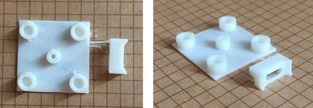
Those settings resulted in the print below. There is a visible improvement. However, light stringing does still occur at the edges of the sockets. Please also note that wet filament can lead to stringing.
Coasting was mentioned multiple times when I searched the internet for solutions against stringing. Before a travel move, it stops the extrusion early to use a certain volume of oozing filament as build material. But in my experiments, enabling this setting and trying different volumes led to identical prints. Coasting is currently marked as an experimental feature.
If the Printing Temperature of the hot-end is lower, the viscosity of the filament increases. That should make it less likely to drip out from the nozzle. I reduced the temperature to the minimum of 195 C for my PLA. But the results were the same to the 200 C I had used initially.
Retraction had by far the largest influence on the print quality. But pushing it too far, is not a good idea as well. Below is a print with 15 mm retraction, which shows almost no stringing. What isn't visible in the pictures is that the dimensions are way off. The diameter of the sockets is not wide enough for the switches to slide inside easily.
Always check your dimensions after you have done adjustments to your print settings.
There are many tutorials, which tell you how to flash the QMK firmware onto a Sparkfun Pro Micro. The official QMK tutorial and their documentation on flashing are great starting points. Nevertheless, I've been running into problems along the way, causing the whole process to take much longer than I have hoped for. In this guide, I will explain the steps I took to finally get the firmware running and how I resolved the issues I faced along the way.
On the hardware side, you need the Pro Micro and a Micro USB cable. I have used the original from Sparkfun, but there exist plenty of clones as well. Just take not that the behaviour might differ from the original one.
The cable was the cause of my first frustration. The Pro Micro was not detected by my PC. There wasn't even this sound you would typically hear when plugging in a USB device. Turns out, the majority of Micro USB cables I possess are charging cables and do not actually transfer data. Only after my fourth or so attempt the microcontroller (MCU) was finally detected. Lesson learned: Don't use just any random cable you can find and make sure it supports data transfer.
I flashed the firmware from a Windows 10 computer. There is no need to install additional drivers. Multiple utilities exist, which can write .hex files into the MCU memory, the most popular being QMK Toolbox and AVRDUDESS. As you will see below, they did not work me. I succeeded when compiling and flashing using the QMK command line interface (CLI).
To make the MCU programmable and appear as a serial device at a COM port in your device manager, it needs to enter the bootloader. Following the official Sparkfun Hookup Guide, this is done by connecting quickly (within 750 ms) the RST and GND pins twice. You are then given 8 seconds to flash the firmware.
The reset for Pro Micro clones might deviate. Try using this alternative procedure.
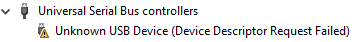
.hex files can be conveniently generated online, for example with kbfirmware, where you can explicitly select the MCU in use (ATmega32U4 in our case). However, flashing with QMK Toolbox resulted in Windows not recognizing the device:
In the device manager, the Pro Micro pops up with as "Unknown USB Device (Device Descriptor Request Failed)":
And this is despite the .hex file being successfully written into the MCU. No error or warning during flashing occurred. Verification of the written firmware passed:
avrdude.exe: verifying ...
avrdude.exe: 13120 bytes of flash verified
In some situations, however, the device was not even able to be programmed. Then QMK Toolbox returned the errors below.
> avrdude.exe: ser_drain(): read error: The I/O operation has been aborted because of either a thread exit or an application request.
> avrdude.exe: butterfly_recv(): programmer is not responding
> avrdude.exe: error: programmer did not respond to command: exit bootloader
The Sparkfun Pro Micro comes in two versions: 5 V running at 16 MHz and 3.3 V running at 8 MHz. What version is used in indicated on the backside of the circuit board. QMK tools seem to assume that the 5 V version is in use, while I use 3.3 V.
In order to indicate the reduced clock frequency, a compilation of the firmware from source was required using the QMK CLI. Refer to the next section for more details. The source files for each keyboard/keymap include the rules.mk file. To set the correct clock frequency, add this line (Reference):
F_CPU = 8000000
After flashing, the Pro Micro got finally recognized as a HID controller.
Before soldering the whole keyboard matrix, I wanted to make sure that both the firmware and the hand-wiring works as intended. Therefore, I've set up a minimal test on the breadboard with three switches wired as a 2x2 matrix. Yellow cables mark the matrix columns, while green...
Read more »I had to position the models diagonally onto the build plate to make it fit. The print time for the case is around 16 hours. Support is needed under the slanted bottom of the case.
After the support is removed (by using a sharp knife for example), thoroughly sand the bottom using grids 120, 240 and finally 400.
Cut a piece of thin cardboard of the same size and shape as the plate. Push it into the case to avoid painting the inner parts, as this might impact the tolerances.
Apply a surface primer, then multiple coats of spray paint (I used Nippon Paint Pylox No. 65 Lily). To make it more durable, use a protective coating (e.g. Rust-Oleum Polyurethane).
Press all switches into the plate. Also assemble the stabilisers and push them through the plate from behind before snapping them in place.
Solder the diodes to one pin of the switches. Connect the switch rows and columns using the thicker 20 AWG solid core wire. Then connect the MCU with the flexible stranded 24 AWG wire.


 Simon Merrett
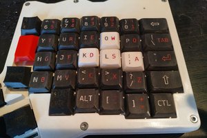
 AberDerBart
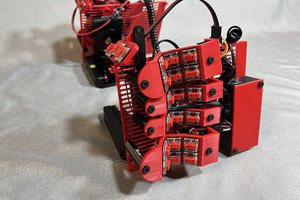
 Peter Lyons
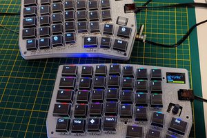
 thpoll