There are many tutorials, which tell you how to flash the QMK firmware onto a Sparkfun Pro Micro. The official QMK tutorial and their documentation on flashing are great starting points. Nevertheless, I've been running into problems along the way, causing the whole process to take much longer than I have hoped for. In this guide, I will explain the steps I took to finally get the firmware running and how I resolved the issues I faced along the way.
The things you need
On the hardware side, you need the Pro Micro and a Micro USB cable. I have used the original from Sparkfun, but there exist plenty of clones as well. Just take not that the behaviour might differ from the original one.
The cable was the cause of my first frustration. The Pro Micro was not detected by my PC. There wasn't even this sound you would typically hear when plugging in a USB device. Turns out, the majority of Micro USB cables I possess are charging cables and do not actually transfer data. Only after my fourth or so attempt the microcontroller (MCU) was finally detected. Lesson learned: Don't use just any random cable you can find and make sure it supports data transfer.
I flashed the firmware from a Windows 10 computer. There is no need to install additional drivers. Multiple utilities exist, which can write .hex files into the MCU memory, the most popular being QMK Toolbox and AVRDUDESS. As you will see below, they did not work me. I succeeded when compiling and flashing using the QMK command line interface (CLI).
Reset to enter the bootloader
To make the MCU programmable and appear as a serial device at a COM port in your device manager, it needs to enter the bootloader. Following the official Sparkfun Hookup Guide, this is done by connecting quickly (within 750 ms) the RST and GND pins twice. You are then given 8 seconds to flash the firmware.
The reset for Pro Micro clones might deviate. Try using this alternative procedure.
Unsuccessful attempts
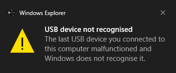
.hex files can be conveniently generated online, for example with kbfirmware, where you can explicitly select the MCU in use (ATmega32U4 in our case). However, flashing with QMK Toolbox resulted in Windows not recognizing the device:
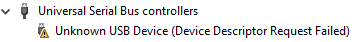
In the device manager, the Pro Micro pops up with as "Unknown USB Device (Device Descriptor Request Failed)":
And this is despite the .hex file being successfully written into the MCU. No error or warning during flashing occurred. Verification of the written firmware passed:
avrdude.exe: verifying ...
avrdude.exe: 13120 bytes of flash verified
In some situations, however, the device was not even able to be programmed. Then QMK Toolbox returned the errors below.
> avrdude.exe: ser_drain(): read error: The I/O operation has been aborted because of either a thread exit or an application request.
> avrdude.exe: butterfly_recv(): programmer is not responding
> avrdude.exe: error: programmer did not respond to command: exit bootloader
Solution
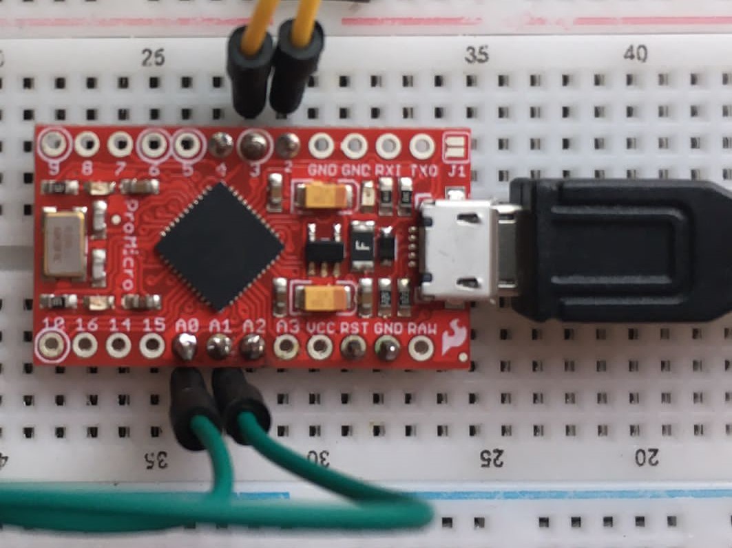
The Sparkfun Pro Micro comes in two versions: 5 V running at 16 MHz and 3.3 V running at 8 MHz. What version is used in indicated on the backside of the circuit board. QMK tools seem to assume that the 5 V version is in use, while I use 3.3 V.
In order to indicate the reduced clock frequency, a compilation of the firmware from source was required using the QMK CLI. Refer to the next section for more details. The source files for each keyboard/keymap include the rules.mk file. To set the correct clock frequency, add this line (Reference):
F_CPU = 8000000
After flashing, the Pro Micro got finally recognized as a HID controller.
Testing the firmware
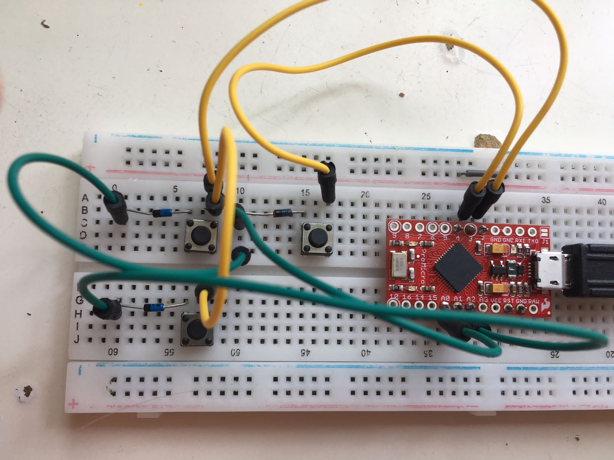
Before soldering the whole keyboard matrix, I wanted to make sure that both the firmware and the hand-wiring works as intended. Therefore, I've set up a minimal test on the breadboard with three switches wired as a 2x2 matrix. Yellow cables mark the matrix columns, while green cables build the rows. Notice how every switch has a corresponding diode pointing column to row.
The firmware files for that can be found in the test repository. To compile, source test2x2.sh from within the QMK CLI. In the firmware file config.h, the pins of the MCU need to specified. They are not the same as the board pins and need to be converted.
After plugging the "keyboard" into the PC, digits 1 to 3 should appear when pressing the respective buttons. Simulating a button press can also be achieved by shorting the corresponding row and column pins. Find out why that is and how the controller reads the switch position in my post on matrix scanning (coming soon).
Discussions
Become a Hackaday.io Member
Create an account to leave a comment. Already have an account? Log In.