 ElectroBoy
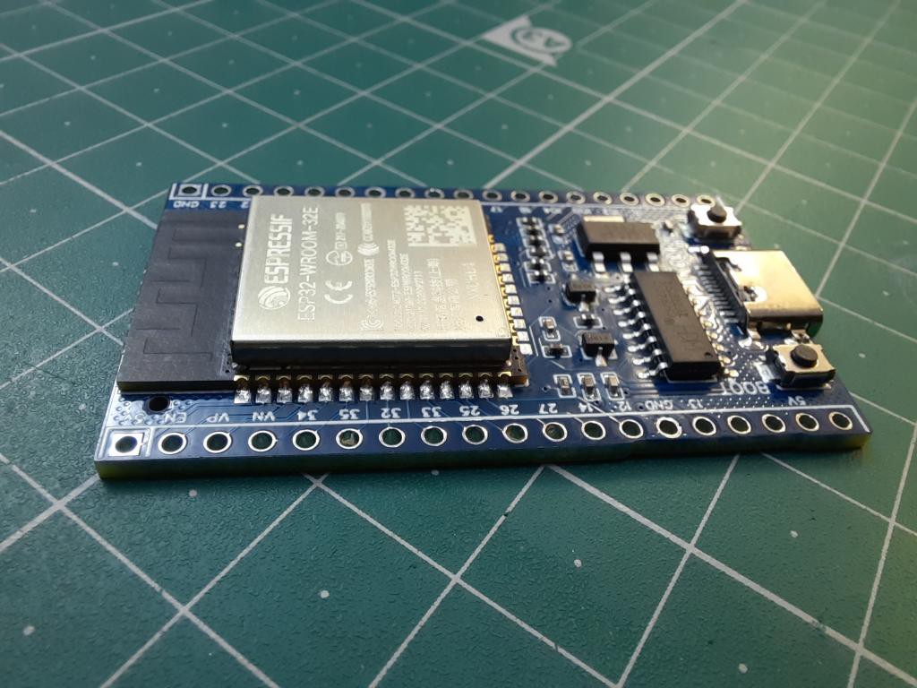
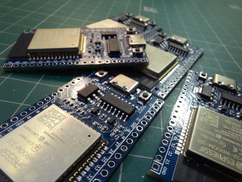
Few days ago, I designed a ESP32 based microcontroller development board. I revealed the Gerber files and SMT process in the previous written “Order with JLCPCB SMT assembly service”. I tested the board with different programs and Wi-fi sharing. And now I am here to show the schematics, circuit assembly and give a full review of this DIY board. Actually, not fully DIY, most of the work is done by JLCPCB SMT assembly service starting from $8.
ESP32 development board:
The ESP32 WiFi and Bluetooth chip is the latest generation of Espressif products. It has a dual-core 32-bit MCU, which integrates WiFi HT40 and Bluetooth/BLE 4.2 technology inside.
Compared to the arduino ESP8266 (the previous generation), the ESP32 wifi and bluetooth chip (also known as ESP wroom 32) has a significant performance improvement. It is equipped with a high-performance dual-core Tensilica LX6 MCU. One core handles high speed connection and the other for standalone application development. The dual-core MCU has a 240 MHz frequency and a computing power of 600 DMIPS.
ESP32 chip (ESP wroom 32) integrates a wealth of hardware peripherals, including capacitive touch sensors, Hall sensors, low noise sensor amplifiers, SD cardinterfaces, Ethernet interfaces, high-speed SDIO / SPI, UART, I2S and I2C, etc.
Features:
- Single or Dual-Core 32-bit LX6 Microprocessor with clock frequency up to 240 MHz.
- 520 KB of SRAM, 448 KB of ROM and 16 KB of RTC SRAM.
- Supports 802.11 b/g/n Wi-Fi connectivity with speeds up to 150 Mbps.
- Support for both Classic Bluetooth v4.2 and BLE specifications.
- 34 Programmable GPIOs.
- Up to 18 channels of 12-bit SAR ADC and 2 channels of 8-bit DAC
- Serial Connectivity include 4 x SPI, 2 x I2C, 2 x I2S, 3 x UART.
- Ethernet MAC for physical LAN Communication (requires external PHY).
- 1 Host controller for SD/SDIO/MMC and 1 Slave controller for SDIO/SPI.
- Motor PWM and up to 16-channels of LED PWM.
- Secure Boot and Flash Encryption.
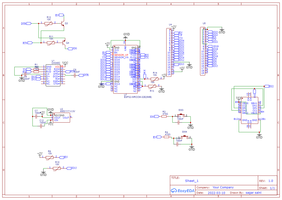
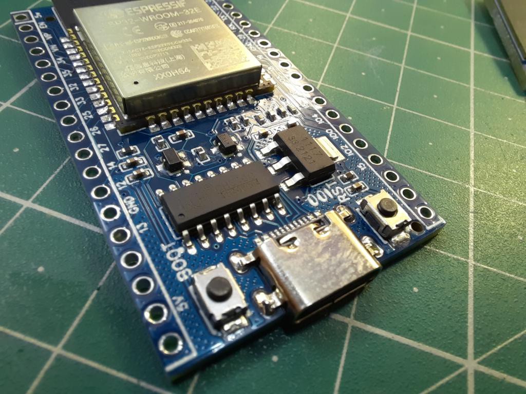
Circuit designs:
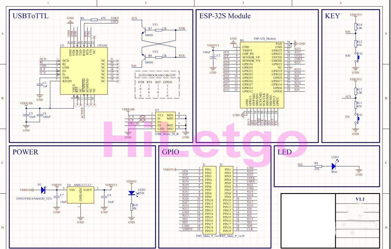
I made the schematics in EasyEDA using the reference circuit from a Japanese webpage. I changed the USB to serial programming chip to CH340g, available easily and cheap. Two transistors are required with this IC to change the general mode of ESP32 into programming mode when compiling of program completes.
Components required:
1) ESP32 Wi-Fi module
2) Ch340g programmer IC
3) 10K, 5k, 1K resistor
4) 100nf capacitor
5) BC547 transistor
6) Usb type C
7) Custom PCB
JLCPCB SMT assembly:
Want same boards as mine, Sign-up using this link and get free coupons of worth $30 for your SMT assembly. Checkout to JLCPCB now and turn your projects into products.
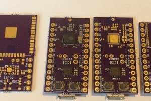
PCB designs:
If you want to use designs then here is the downloading link, all the 3 files Gerber, BOM and CPL is shared. So, you can try SMT service form JLCPCB.
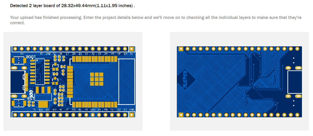
Here I am using blue color, HASL finish, 1.6mm doubled layered PCB. I adjusted the components to match the parameters with original ESP32 boards available in market.
Working:
I tested this ESP32 module with 7 segment display, I got the files of 7 segment display from a friend on Instructables. This program is to display numbers on the LCD.
Also, I noticed that there is an issue with my designs, when upload the sketch programmer will not shift into programming mode automatically. So, we have to give an external trigger by pressing BOOT and FLASH button. I think transistors are not working properly. Well, I will update the schematics again and then try again with new designs. Here is small video of upload sketch to esp32.
Troubleshooting:
1) If you are not using SMT service then make solder joints correctly.
2) Don’t heat the Wi-Fi module too much, when soldering.
3) If microcontroller doesn’t switch to programming mode then reboot and flash the controller using tactile buttons.

 Kris Winer
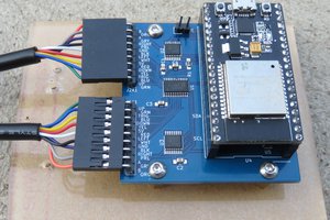
 mulcmu
 Abraham
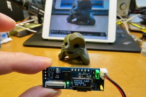
 kodera2t
Hey .. I made my own also, but in a Super Mini form factor since I only need a few GPIOs and no BT or WiFi .. https://oshwlab.com/samm928/esp32d_micro_18pins