Close
0%
0%

Suricata

Wireless indoor environment station that monitors temperature, humidity, light intensity, sound intensity and gases.

Similar projects worth following
The Suricata project consists on the development of a portable device that can be installed inside any house room, and it is able to measure the room temperature and humidity. These data can be shown via a screen on the device or accessed remotely via a mobile app. Besides temperature and humidity, the device may also be able measure light intensity, sound intensity and gases. The data should be acquired at regular intervals allowing for some statistics to be generated. The data can be stored on an SD card, or to a remote server, which can be the main unit in a domotics context. The communication protocols used are BLE and/or Wifi. The BLE is used to communicate with the mobile app and eventually with the main domotics unit. The Wifi is to communicate with the main domotics unit and to access cloud weather services for weather forecast. The last possible functionality is the capability to operate as a thermostat, i.e., to control an AVAC system.

Context


The idea for this project grew from the need to assess the temperature and humidity of my child’s bedroom. At the time, he was almost one year old and the house was pretty cold and humid. It was important to know the room temperature to evaluate the need to go there to check if he was properly covered, or, to turn the heat on, or even to remotely control the heater like a thermostat. With this in mind, I decided to create a device that could measure both the temperature and humidity and provide that data directly via a screen or remotely via a mobile app.
At the time I ended up leaving the project on the shelf after a quick breadboard prototype. At this moment, I decided to resume the project with some additions to the initial concept.
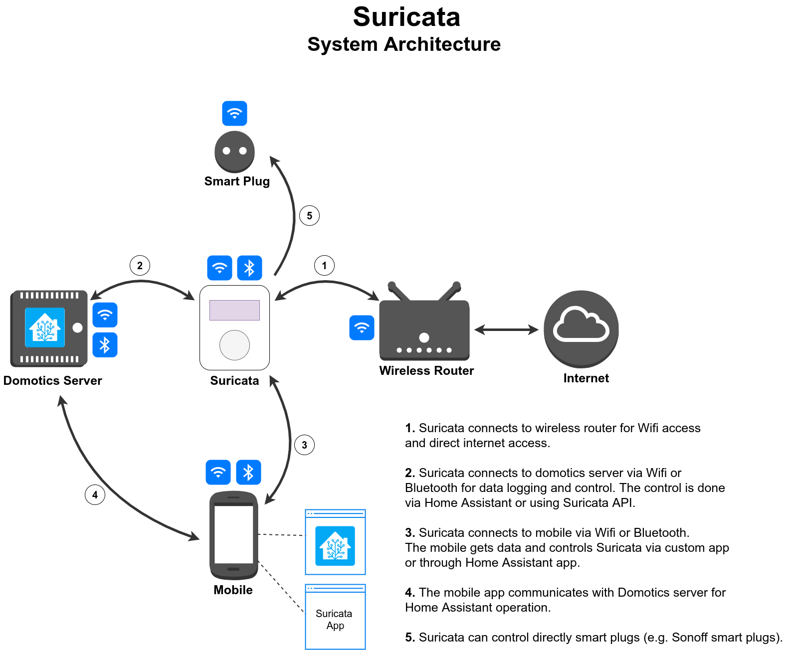
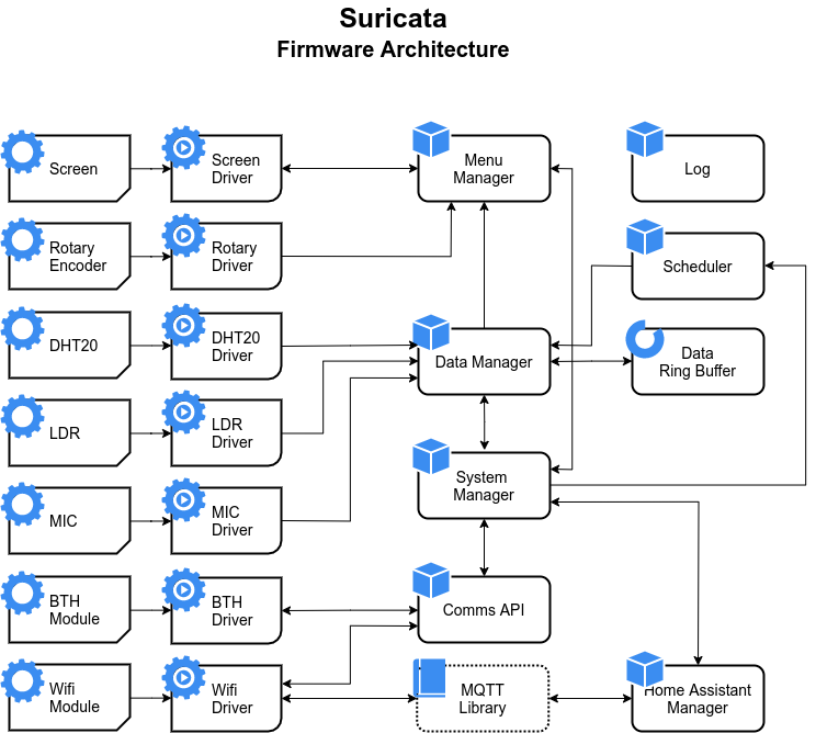
System Architecture

Goals & Milestones


Major Goals

  1. Power: the device must be battery powered to allow an installation anywhere inside a room, and also to allow an easy relocation to a different place or room. However, there should also be an option for plugged power, via USB. The battery level should be measured and shown on the screen and mobile app.
  2. Temperature & Humidity assessment: the device must be able to measure the room temperature and relative humidity. The temperature resolution cannot be greater than 1 ºC. The relative humidity resolution must be less or equal to 5 %.
  3. Data acquisition: the data acquired should be sampled at regular intervals that can be configured by the user via the mobile app, within certain limits. When the user reads the data directly on the device, via button control, the data should be acquired at that moment.
  4. User interaction: the device should have a screen to show the data and some buttons for device control. The screen should allow to draw small icons and text (be pixel-based), not like a normal LCD screen with lines and columns. It can be monochromatic.
  5. Communication: the device should be able to communicate via BLE and Wifi.
  6. Shape & Size: the device case should be small, allowing the device to be comfortably held with one hand. It should have supports to hang on a wall and also to stay on top of a table or furniture. The small size and weight should contribute to portability.
  7. Mobile app: the mobile app is used to control the device and should have the following features:
  • Take a measurement;
  • See sensor statistics reports for various periods: hour, day, week.
  • Configure Wifi connection;
  • Configure data acquisition rate;
  • Configure SD card clean period;
  • Read SD card stored data;
  • Select weather forecast channels;
  • Connect, register and control various devices at the same time;
  • Show the battery level;

Minor Goals

  1. Data storage: the device should have internal data storage via a micro SD card. The data can be read via the mobile app or a central domotic unit. The user can configure the data duration on the card. When that duration passes the card is wiped out and new data is stored. If the card should fill up to maximum, a notification should be sent to the user that the card will be wiped after a certain time. This allows the user to download the data if it wants to.
  2. Light, audio and gas data assessment: the device should be able to measure the light intensity inside the room, differentiating between darkness and several levels of light. It does not need to measure LUX directly. It should also measure audio levels. It is not about recording the sound waves but the sound intensity. We do not need audio information, only dB information. If possible it would be nice to have also some form of gas measurement. Maybe CO2 levels, or stove gas presence. The inclusion will depend on the dramatically on the available sensors and price range.
  3. Weather forecast: when using the Wifi connection, the device can access some weather forecast channels to download the forecast for the current day. The weather channel used can be chosen on the mobile app, from a list of available services.
  4. Control AVAC devices: the device can turn on/off a heater, or control an AC system. The...
Read more »

suricata_v1.0-F_Mask.pdf

PCB Layout Front Mask

Adobe Portable Document Format - 58.18 kB - 05/22/2022 at 23:11

Preview
Download

suricata_v1.0-B_SilkS.pdf

PCB Layout Back Silk

Adobe Portable Document Format - 21.18 kB - 05/22/2022 at 23:11

Preview
Download

suricata_v1.0-B_Mask.pdf

PCB Layout Back Mask

Adobe Portable Document Format - 18.20 kB - 05/22/2022 at 23:11

Preview
Download

suricata_v1.0-GND_Cu.pdf

PCB Layout GND

Adobe Portable Document Format - 27.40 kB - 05/22/2022 at 23:11

Preview
Download

suricata_v1.0-F_SilkS.pdf

PCB Layout Front Silk

Adobe Portable Document Format - 24.18 kB - 05/22/2022 at 23:11

Preview
Download

View all 21 files

  • 1 × Arduino Nano 33 IoT Main control unit.
  • 1 × DHT20 Temperature & Humidity sensor
  • 1 × SPU0414HR5H-SB-7 Microphone
  • 1 × SMT-0540-S-R Electronic Components / Misc. Electronic Components
  • 1 × LDR Resistor Networks / Thick Film Networks

View all 27 components

  • It's alive!

    Ricardo Tonet07/23/2022 at 00:42 0 comments

    I've been working slowly on the firmware side, although free time is becoming a rare commodity on my side.

    While starting the firmware development I noticed a few more schematic and PCB mistakes. One of them was major. During schematic I misplaced one position in a few Arduino socket pins. I ended up connecting the GND plane to the Reset pin instead of the GND pin. This left the Arduino on reset. I had to cut the Arduino reset header pin to prevent it to touch the socket. I also had to shunt two socket pins, and break the buzzer lane and connect it to the right pin with a wire to the PCB bottom.

    The other mistake was again a footprint inversion. I ended up flipping the buzzer polarity. It does not seem to work at the moment, probably it is broken. Have to do a little more debug on that. Definitely, there must be a PCB version 1.1.

    Besides this, everything else so far seems to be working fine. I only haven't tested the screen and rotary encoder.

    At the moment, I've already done the LDR, LED, MIC and DHT20 drivers. I can read their values and print on the serial console. The LEDs can also turn on/off, blink at chosen frequencies and fade in/out. For the LDR and MIC I tried to calculate the LUX and sound intensity in absolute dB, but the values are not correct. For the LUX I tried a quick calibration using a mobile phone lux meter app, but I need more points to find the right calibration curve. For the sound intensity I used the mic datasheet data and a few equations for the conversion but something is off. I will fix it later.

    Right now, Suricata is ALIVE!!!

  • PCB Assembled

    Ricardo Tonet06/09/2022 at 01:39 0 comments

    Finally I have my PCB assembled. I took me a while because I was assembling 5 PCBs at the same time, although, only one is complete. I did not buy all the components for the five of them. I will later on.

    During assembly I also noticed a few mistakes on the PCB. The component A2 is a boost step up breakout board to 5V. I switched the Vin and Vout pins on the back footprint, so I had to solder the component in the front.

    The component A1 is a LiOn battery charger breakout board. I forgot to connect the GND to the battery (-) connector on the schematic and PCB. I ended up making a solder bridge between the two pads directly on the breakout board. I tested the Power supply and it seems fine. This component also has the pad description footprint showing on the front instead of the back.

    I already started the final fw with arduino on the breadboard. After fully testing the board I will start to develop directly on the PCB.

    Here are the assembled PCB pictures:

  • Firmware Architecture

    Ricardo Tonet05/24/2022 at 01:02 0 comments

    Defined the firmware architecture to start implementing soon.

  • Current Status

    Ricardo Tonet05/22/2022 at 02:12 0 comments

    At the present moment, the first prototype already has the PCB manufactured at JLCPCB.

    The components were also purchased and the soldering will start soon.

    The firmware development will also start soon, first on the breadboard setup, and later on the final hardware, once assembled.

View all 4 project logs

Enjoy this project?

Share

Discussions

Similar Projects

Does this project spark your interest?

Become a member to follow this project and never miss any updates