 danjovic
The BASIC interpreter of MSX computers was designed to allow the expansion of many of its functionalities by using hooks, which are addresses called from strategic locations within the BIOS. Each hook code takes 5 RAM addresses that are initialized with Z80 RET instrucions. Then to expand a given function it is necessary to replace the RET instructions by a CALL to the address where the expansion code is located.
The HLPT is located at address 0xFFB6 and it is called by the LPTOUT function which is the standard routine to output a character to the line printer via the Centronics Port. Any instruction of the BASIC interpreter that uses the printer make a call to the LPTOUT function and hence make a call to the HLPT hook.
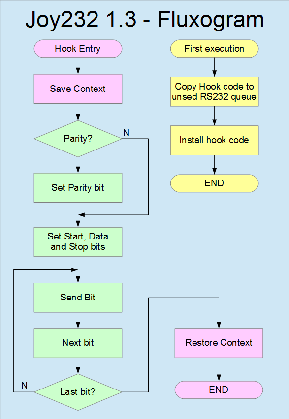
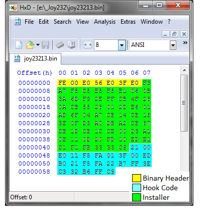
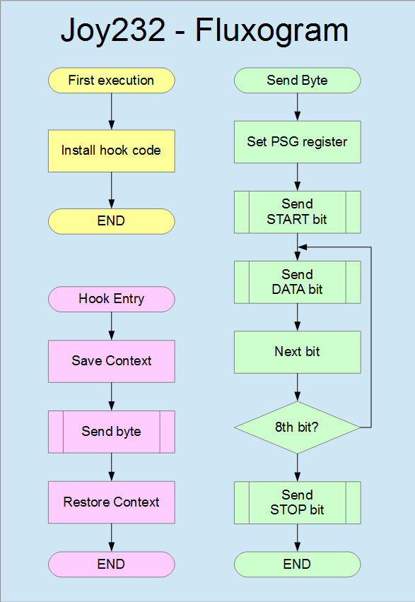
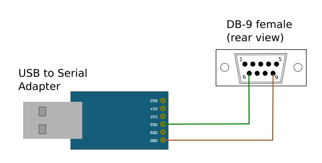
The Joy232 code is straightforward. The first time it runs it replaces the RET instructions on the HLPT hook by a CALL to the address of memory where the serial transmission is performed. After the hook code is installed any character sent to the printer will be sent serially to one pin of the joystick port.
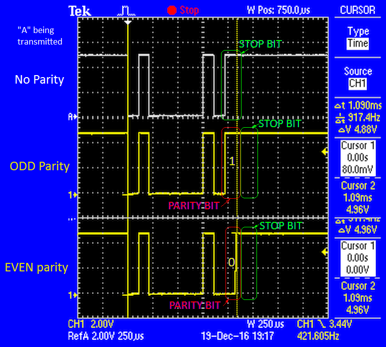
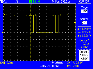
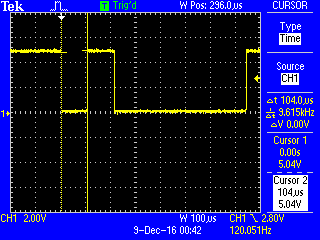
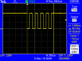
The bitbang code concatenates a bit sequence composed by the start bit, the data bits and the stop bit into a 16 bit register. Next each bit is transmitted until 10 bits have passed. After the last bit is sent the routine ends and the control returns to the BIOS.
The baudrate can be controlled by changing the value BAUD either on compilation time or by a poke (after the hook code is already installed). The lowest baudrates allow some tolerance on such value which is indeed used in a delay loop.
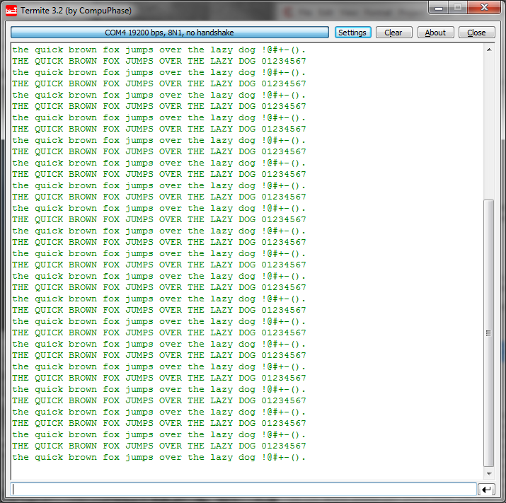
The program can be loaded on the MSX machine as a binary (using BLOAD instruction) or can be typed in from a BASIC prompt.


 Paul Robson
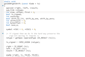
 Ken Yap
 Boelens, Leland
 Keith
Keith