Purpose of the system
I made a resistivity meter to perform basic archaeological geophysics in a field. One of the time consuming things is to map the measurements on a grid. Typically cords (0.5m apart) are laid out on the ground for this.
It would be easier if I could just walk the field, and have the position of each measurement stored along the resistivity data.
Centimeter accuracy is possible with GNSS ( e.g. RTK ) but this was too complicated or expensive for me.
That's why I made this sound based system. It is tested in a 25x25 m area but with small alterations (mostly sampling longer) it should work in a much larger area. (e.g. 75x75m ).
Most information is in this video :
here some extra's :
Why use audible sound instead of ultrasonic ?
- audible sound works with a lower sampling frequency (I use 60KHz). So less processing needed and faster.
- The attenuation of ultrasound in air is much larger.
- The high quality factor (Q) of ultrasonic transceivers makes them difficult to use. You cannot transmit short or wide bandwidth signals with them.
3D printed parts
My son is the 3D designer and he uses fusion-360 (for personal use) like a pro.
Electronics
I wanted to use a Texas Instruments CC1312R (High-Performance Sub-1 GHz Wireless MCU) because it has great specifications and is low-cost. ( only a few Euro's). The 0.5mm pitch made it a bit difficult to manually solder on a pcb though.
I looked at modules containing this chip and settled for a module from an Italian company Radio Controlli. (https://www.radiocontrolli.com/rc-cc1312r-868). It works great!
The prototype is a bit over designed to make it easier to experiment. Eliminating one of the op amps and one of the voltage regulators is possible.
The PCB only has tracks on the top side, the bottom is a complete ground plane. this makes it easy to etch at home.
As you can see in the movie I use a simple wire antenna. I started with a quarter wave length wire ( 8.6cm ) and then cutoff small parts until the RSSI of received telegrams is maximized (use SmartRF Studio 7 for that). The size and orientation of the wire is not critical. The range is tested to be at least 100m, but should be more then 300m if properly tuned.
Debug & development tools
- For Programming and debugging I use the LAUNCHXL-CC1312R1 development kit. (https://www.ti.com/tool/LAUNCHXL-CC1312R1).
Software in X, 0, M
- See included source code.
- All devices use the same code base. At startup the status of 2 pins is read, and this determines how the software behaves.
- It is written in C with Code Composer Studio V10.2 IDE.
Debug and visualization c# application
- See included source code.
- This is a quick and dirty implementation, as it was only needed for development, not for using the system with the resistivity meter.
- It is a c# windows form app, written in Visual Studio Community 2019.
 Ted Yapo
 C̐ͪhris Q҉͚͙uites
 Philip
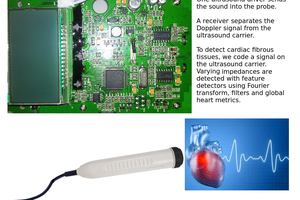
 Jean Pierre Le Rouzic