 Timo
TimoThis is an update which explains the schematic of the Control Station. I also finaly uploaded all schematic files for the project and the software in its curent state.
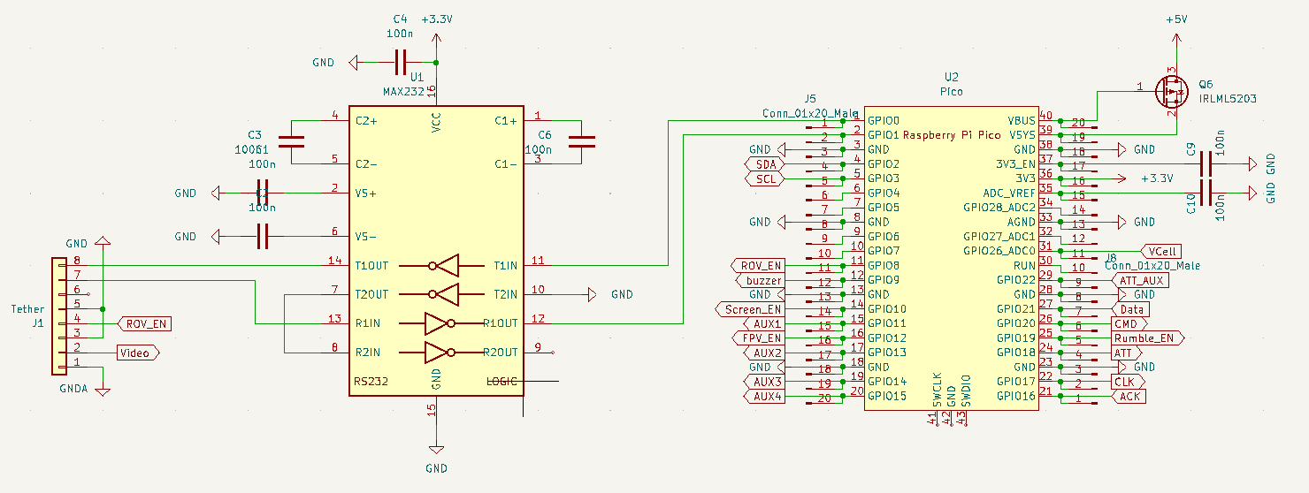
In Fig. 1. you can see the RPi Pico of the Control Station and its pin connection. The Pico is supplyed with +5V which is generated on the pcb by the circuit in Fig. 2.
The MAX232 translates the UART to RS232 to make the communication more robust. Its connected exacly like in the application example from the datasheet, so no suprises here. Just one thing: the MAX232 is supplyed with 3V3 from the RPi Pico. This is important because not all versions of the MAX232 work on 3V3, some need 5V.
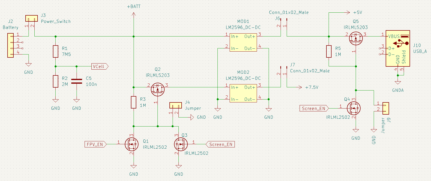
A 3 cell LiPo battery is connected via J4. An On-Off-switch is connected via J3, The voltage divide R1, R2 divides the battery down by a factor of 3,75 so that the RPi Pico can measure its voltage via its ADC.
A LM2596 SMPS modul (MOD1) generates +5V from the battery voltage to supply the RPi Pico. Additonaly the +5V also provide power to the CCTV screen via (power only) USB.
The power of the CCTV screen can be turned off via Q5. Q4 is used as a level shifter so the Pico can switch the 5V power supply. The jumper J9 can be set to override the Pico and just turn the screen on for debuging purposes.
A second SMPS modul (MOD2) generates +7V5. This is the analog supply voltage for the video spliter and the FPV video transmitter TS5828. It is also used for the rumbling function of the PS1 controller. This might lead to artifacts in the videosignal down the line but ... fuck it.
The analog supply can be turned off via Q2 in the same way as the +5V supply.
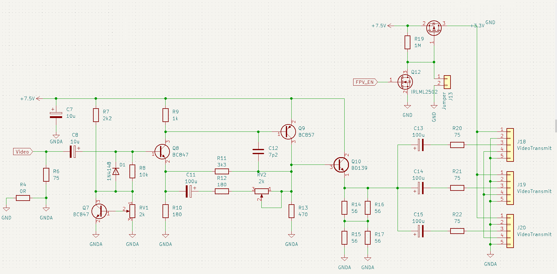
Because i want to be able to use the FPV and the CCTV screen at the same time i need a buffer to drive two video sinks at the same time. The schematic is stolen from: https://www.electronics-lab.com/project/3-channel-analog-video-splitter-with-video-amplifier/
TLDR: The amplifier has an input impedance of 75Ohm. It amplifies the input voltage by a factor of two. It has three outputs each with a an output impedance of 75Ohm each. The inputs of the CCTV screen and the FPV transmitter are 75Ohm as well.
So the amplifier amplifies by a factor of two and the voltage divider of output and input impedance divides it down to a half. So it is effectivly a buffer with three outputs.
Oh, the OLED display and the piezospeaker are directly hocked to the Pico.
Discussions
Become a Hackaday.io Member
Create an account to leave a comment. Already have an account? Log In.