 conradcn
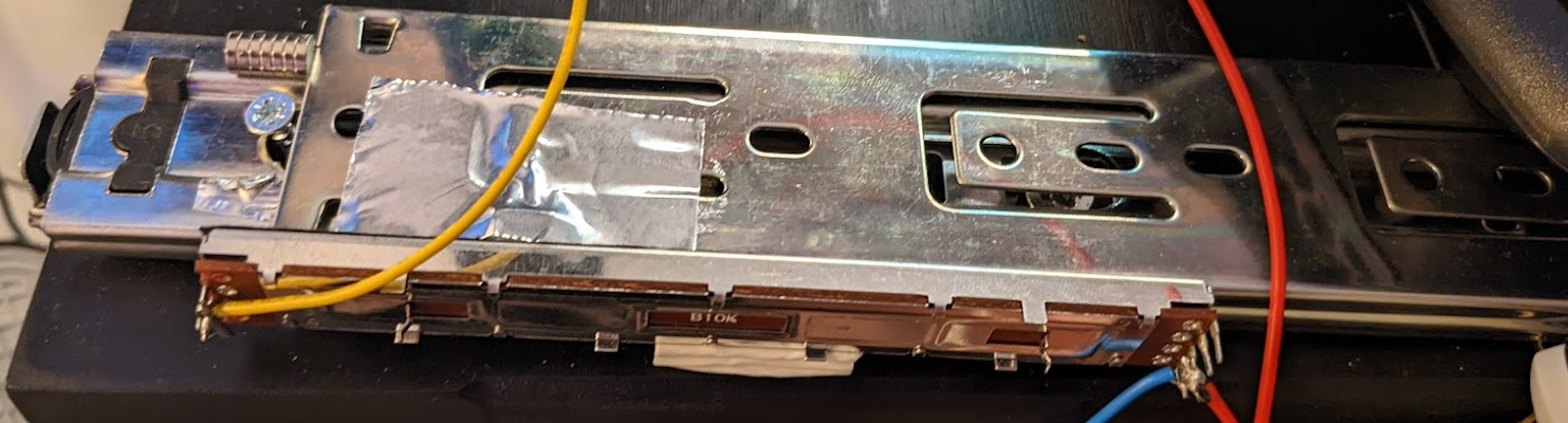
In addition to the traditional pitch axis bound to pushing the wheel in and out, I added a yaw axis by allowing the wheel to pull differentially on the two drawer sliders. The math is very simple; the pitch is simply the average of the two potentiometer inputs. The yaw is the difference between the two potentiometer inputs. Finally, the roll is just bound to the main steering wheel axis. Throttle is bound to the pedals, making this a true space bus. Rather than calibrating ranges on the Arduino, I opted to use the built in windows controller calibration so that I could tweak it on the fly.
This device is insanely simple. There are two drawer sliders screwed to a piece of scrap wood. I left the back screws sticking out enough to block the second stage from moving, as the travel ended up being a lot longer than I needed. I also taped a few neodymium magnets to the back, which lock the wheel in place when not in use or for racing games that don't take advantage of the extra axes.
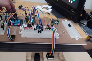
Electronically, everything is just wired into an Arduino Pro Micro, which poses as a game controller.
I've done a few trade runs in my Type 7 (with manual landing, because those extra four cargo slots are everything). The lack of any thruster control reduces the margin for error, but the overall system works astonishingly well. The extra axes are intuitive because they match cleanly with ship motion, and it wasn't long at all before it felt automatic.
 deftcoyote
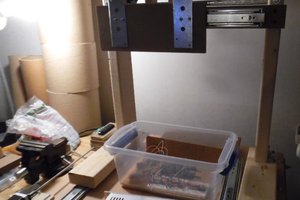
 cyplesma
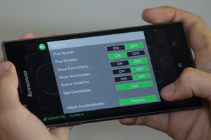
 DoctorCharmQuark
 Robbo
Robbo