 Peter Walsh
Measuring the current draw from pager motors physically difficult, and I wanted to do another "motor survey" to get a handle on the current draw, so I decided to build a jig for easy measurement.
Now I'm perfectly aware that power supplies will show both voltage and current, but display isn't the issue: making contact with tiny wires is the problem.
After some brainstorming, I decided that a thick gauge wire wrapped across the top jaw of a clothespin, pinching the wire against a flat piece of PCB would provide a good contact for short lengths of tinned wire ends.
The system uses an embedded DVM to show the current. Harbor Freight was giving these away for free, and I managed to snag some to embed into projects. You can get them for about $5 on eBay, with free shipping.
In practice, you set your power supply to the voltage you need, then either:
- Open the clothespins, and close them on the tinned ends of the wires
- Touch the tinned ends of wires to where the two landing pads
- Slide the wires along the landing pads, until they get pinched between the pad and thick wire.
In practice, the last 2 methods proved the most convenient.
Materials needed
- Cheap DVM
- One pair of terminal posts
- Two clothespins
- Short length of thick wire (such as 14 gauge)
- Stiff cardboard, or 1/8" plywood
- 4 button feet
- A tiny piece of copper-clad PCB
Tools needed
- Laser cutter
- Hot glue gun
Construction
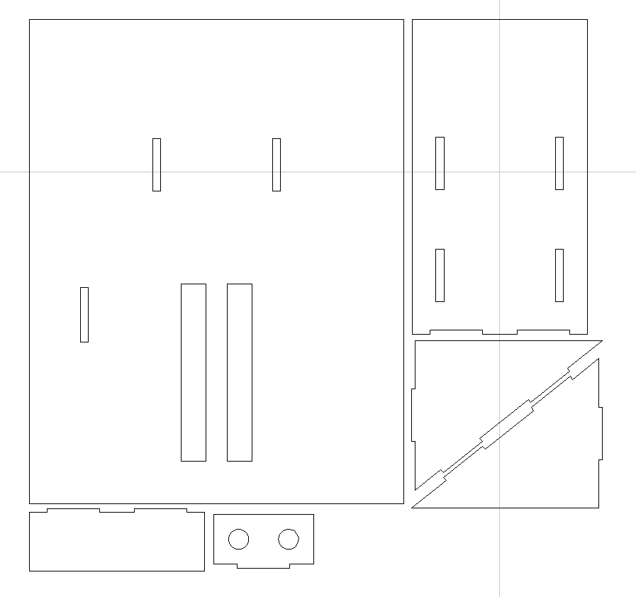
(NOTE: The design files are available either in the project main page, or on GitHub referenced from the main page.)
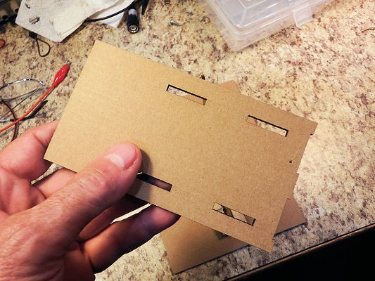
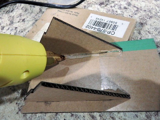
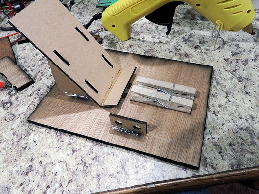
The cardboard is assembled using "slot and tab", with hot glue to hold everything together.
The jig can be made from 1/8" plywood, but it actually works quite well when cut from stiff cardboard. I made my actual device with 1/4" wood as a base, and used the cardboard pieces for everything else.
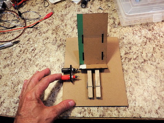
A quick demo test of the original design. Hmmm... the DVM holder should be moved back a bit. Update the design.
Cut the wooden sections.
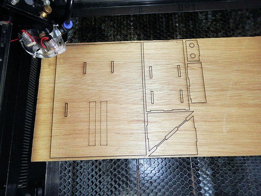
And glue the pieces together.
I realize that you can make pieces that snap together in various ways, but doing that requires you to dial-in your laser cutter for a snug fit, and a lot of people don't do that or don't know how to so that.
Essentially, "snap together" joins are fine if you're making many dozens of copies, as for a product, because you can tune your design to the exact thickness of material.
For a one-off jig, hot glue and large, easy-to-assemble slots is much easier.
The base has an etched pattern (not holes) to indicate where the clothespins go.
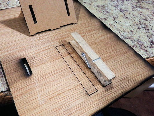
Hot glue the clothespins into position.
Gluing complete.
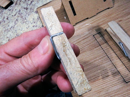
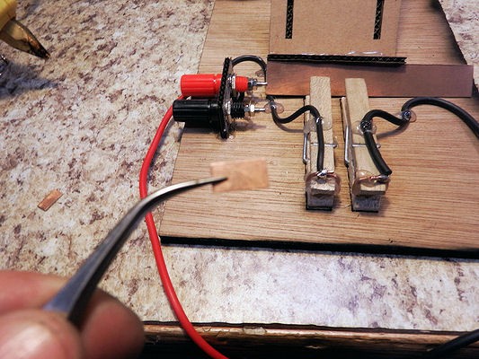
Take a piece of thick wire, such as 14 gauge (a short length of stripped Romex works well) and bend it around the end of the clothespin as shown.
This will make a rounded, cylindrical contact with the landing plate. A wire placed in the jaws of the clothespin will be pinched against the wire and the landing plate, making a good contact.
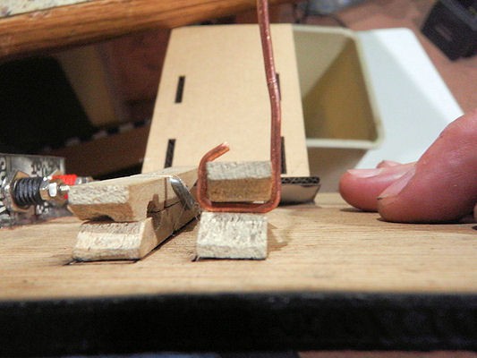
Side view of the wire contact.
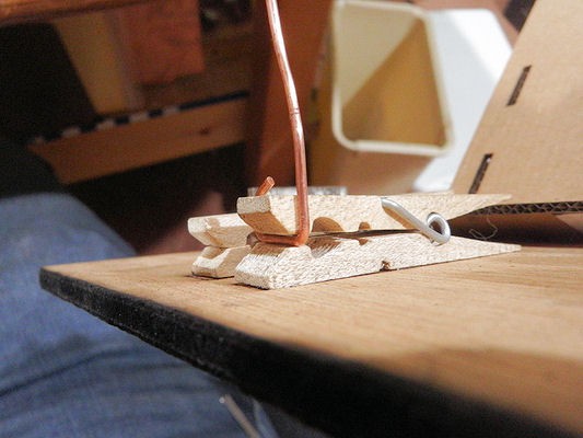
Trim and complete the wire contact as shown. Note that one side of the wire higher than the top of the clothespin, leaving an underpass. A connection can be threaded through the underpass, and soldered.
Glue the wire contact in place.
Side view of glued contact. Looks messy, eh?
Completed wire contacts, glued into place. Looks *really* messy, but that's OK!
Connect everything together. Red post -> Ammeter -> Right clothespin. Left clothespin -> Black post
Hmmm...
1) The posts extend beyond the edge of the board, and
2) The post connections are unshielded (from your hand, for example) which might be a problem if the device is used for other (ie - high voltage) purposes.
FIXED: The new design moves the terminal posts to the UL corner, where they are out of the way, and inset sufficient so that they don't stick out.
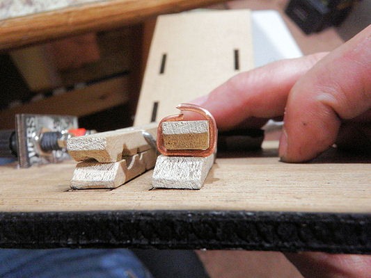
Cut a small piece of PCB to act as landing pad for the wire electrodes. The piece should be as wide as the closepin jaw, and 3x or 4x the the thickness of the wire.
Coat the back of the landing pad with glue, place onto the bottom of the jaw, and allow the wire to press against the landing pad until the glue cools.
This looks misaligned, but that's because the wire is misaligned and probably not straight, due to bending. The pressure from the clothespin actually aligns the landing pad with the wire, making a snug fit.

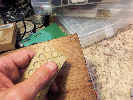
Add a few button feet to the back. This gives a nicer feel to the device, and keeps it sliding around if you need to manhandle something into the jig.
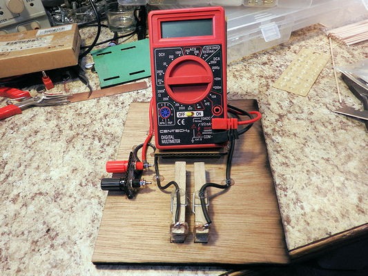
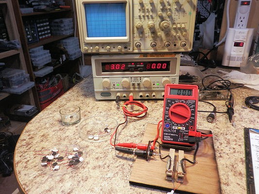
Here's the finished jig. I'm using hot glue to dress the wires, because it's rapid development and I can't be bothered with doing it the right way...

And here's the device, setup and ready for the motor survey.
Discussions
Become a Hackaday.io Member
Create an account to leave a comment. Already have an account? Log In.