SmartScale Video Demonstration
Project Overview
SmartScale was developed in 10 weeks as part of the EE 327: Electronic System Design II course at Northwestern University. The instructor was Professor Ilya Mikhelson, PhD. For the build process, we completed 5 milestones, roughly equally spaced every two weeks. The first milestone was simply a Project Plan, where we outlined all of our parts and goals for the product. The second milestone was an initial prototype, where we demonstrated functionality of the load cell (scale) and Tornado server. The third milestone was a full prototype, where we added in functionality for the ESP32-CAM camera, the Google Cloud Vision API, as well as the USDA FoodData Central API. The fourth milestone was a first revision, where we finalized the 3D printed hardware for the device as well as feedback in the form of LEDs. Finally, the fifth milestone was a second revision, where we added in the webpage as well as performed final testing.
Build Process
As a brief overview of the design process, after initially outlining the data pipeline and required hardware components via the system flow chart, we began with getting the load cell up and running as a functional scale. We 3D printed the necessary plates to interface with the load cell, and after wiring it with the HX711 amplifier, we used a set of calibration weights to generate a calibration curve and thus a necessary calibration constant for accurate measurements. We then interfaced this with the ESP32 via a 2 wire communication protocol (clk and dat) based off of I2C principles.
The next main phase of the project was developing the backend server architecture that could receive weights (in the form of floats) and images from the ESP32 CAM. These were delivered in POST requests with specific content headers. The server itself was hosted on a local PC.
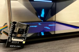
While server development was ongoing, we looked to get a functional image pipeline established with the ESP32 CAM including how to take, store, and process images with the eventual goal of packaging them in a post request to be sent to the server.
Once images and weights could be sent to the server, we looked to develop a processing procedure to extract the appropriate food label and macronutrient information. We did this utilizing Google Cloud’s Vision API, specifically making use of the label detection method. This returned a potential list of image labels which we cross referenced with our local food inventory. Finally, we looked to the USDA FoodCentral API to gather the relevant macronutrient information.
With all the required information held locally on the server, the last step was to populate a webpage for the user to view their information. This was accomplished by rendering an HTML page passed in specific variables of interest like food name, protein, fat, and carbohydrate content.
System Overview
The SmartScale system contains 10 basic components as outlined below:
- ESP32-CAM
- Scale
- Camera
- Battery Pack + Voltage Regulator
- Tornado Web Server
- Food Macro Database
- Cloud Image Recognition
- Public Webpage
- 3D Printing
- Push Button + LED Feedback System
The hardware components as well as the interaction of these systems are neatly outlined in the following figures.


ESP32-CAM

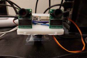
Scale
The scale is the backbone of this entire product, and contains a number of individual parts to make it work. The first is a 1kg load cell purchased...
 Yi-Wei Chen
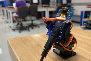
 Nathaniel Wong
 Antony, BumJoon, Peter