 Manuel Tosone
How it Works
The signal flows through three stages. It is first amplified by a variable gain amplifier then distorted and finally buffered by the output stage.
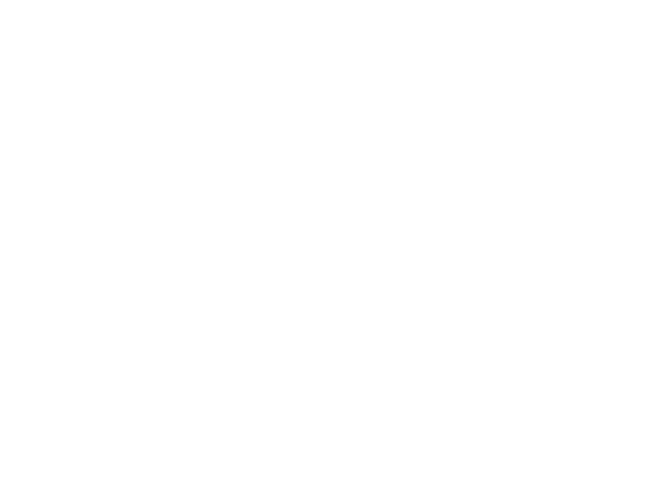
Input Stage
The Input Stage is a variable gain amplifier with a high input impedance that boosts the signal from the guitar to a level that can drive the following stage.
The first thing that the signal encounters, coming from the audio jack, is resistor R1 and diodes D1 and D2 for overvoltage protection.
Q1, Q2, and Q3 are part of a feedback loop where the high input impedance is achieved with a differential pair.
The feedback loop tries to keep the voltage of the bases of Q1 and Q2 the same. Raising the voltage on the base of Q1 will make it conduct more, this will make Q3 more conductive and it will increase the voltage on the base of Q2, with Q2 conducting more current the drop on R7 increases thus making Q1 less conductive.
C5 sets the low cut-off frequency. For high enough frequencies C5 is a short circuit and the gain of this stage is dictated by R10 and R9 with the classic noninverting formula (A = 1 + R10/R9). At low frequency C5 is open and the gain drops to unity.
The lower cut off is given by
C4 sets the high cut-off frequency. For high enough frequencies C4 grounds the base of Q3 effectively breaking the loop and lowering the gain. Determining the exact cut-off frequency is not as straightforward as before because it depends on the open-loop gain of the amplifier, with a 47nF capacitor it's around 6 to 8 kHz.
The gain is set with the potentiometer RV1.
Q4 is wired as an emitter follower to get a low enough impedance to be able to diìrive the next stage. RV2 is used to set the DC bias for Q4 and the following stage. C11 is a bootstrap capacitor, it's there to increase the impedance seen by RV1.

Distortion Stage
This is a logarithmic amplifier. There are 6 gain stages, the signal enters the base of all stages and the outputs are summed together.
Moving left to right on the schematic the gain increases in powers of 2. The first stage has a gain of 2, the second has a gain of 4, and so on with the last having a gain of 64.
With a small input signal, none of the stages saturates and the output will be an amplified version of the input with no distortion. Increasing the input signal will make the stages saturate in sequence, progressively reducing gain and adding distortion.
The gain of each stage is roughly given by the ratio of the collector and emitter resistors (with higher gain the transconductance of the BJTs must be taken into account). To decouple the gain from the DC bias the emitter resistance is split between two resistors in series. The total resistance is always roughly the same, so all the stages are biased to the same point. The capacitor is a short circuit for the signal, the gain is set by grounding the signal at different points.

Output Stage
Another feedback circuit, this time a transimpedance amplifier i.e. does a current to voltage conversion. It is very much like an opamp summing amplifier.
The gain is given by the resistor R28 and the output impedance of the previous stage (330KΩ / 6).
C16 sets the high cut-off frequency.

Power Supply
Pretty simple stuff, the +9V comes directly from the battery, and +6V is regulated by an LDO.
The DC bias for all stages derives from the +6V so it must be regulated. The NCP711 has a typical ground current of 325uA.


 Jesse
Jesse
 Burkhard Kainka
 Bud Bennett
 Adam Gulyas
That project looks great ! The explanations are very useful !