 Upkie Zero
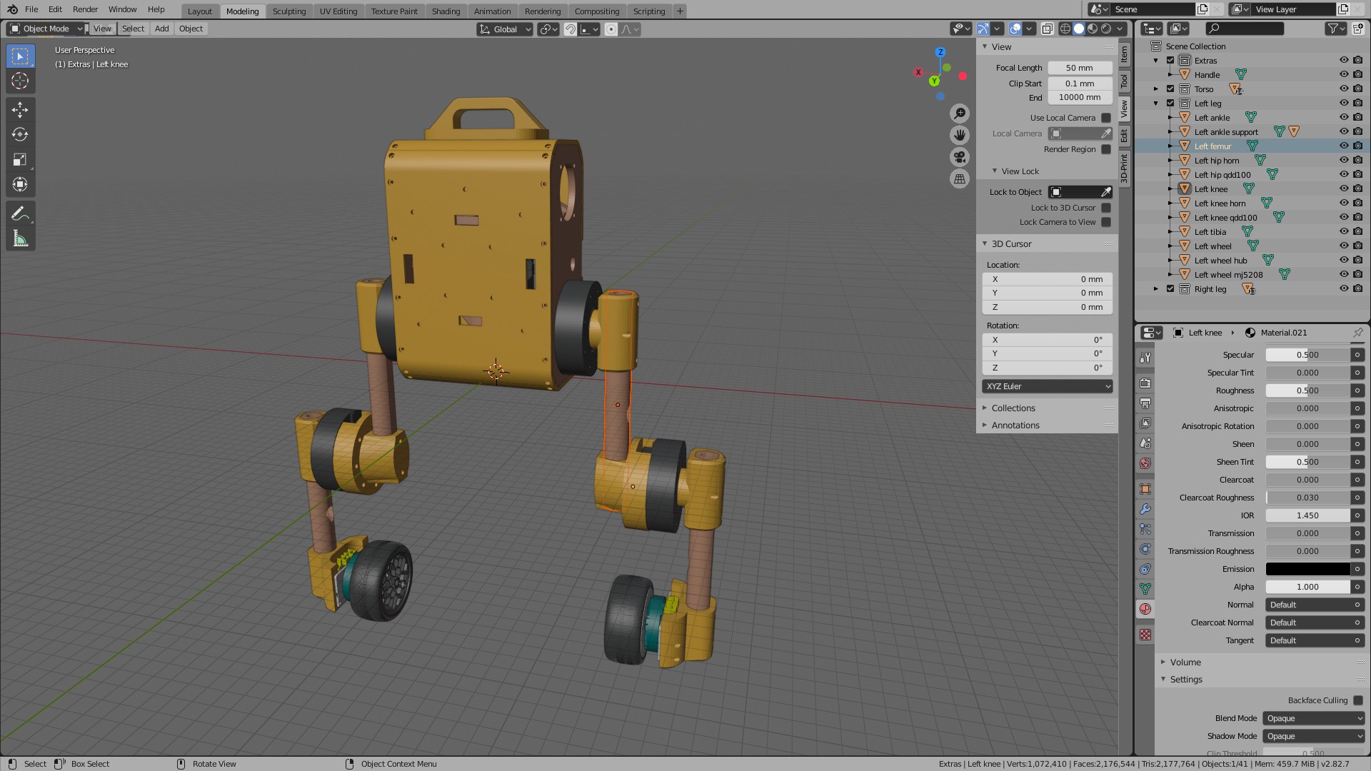
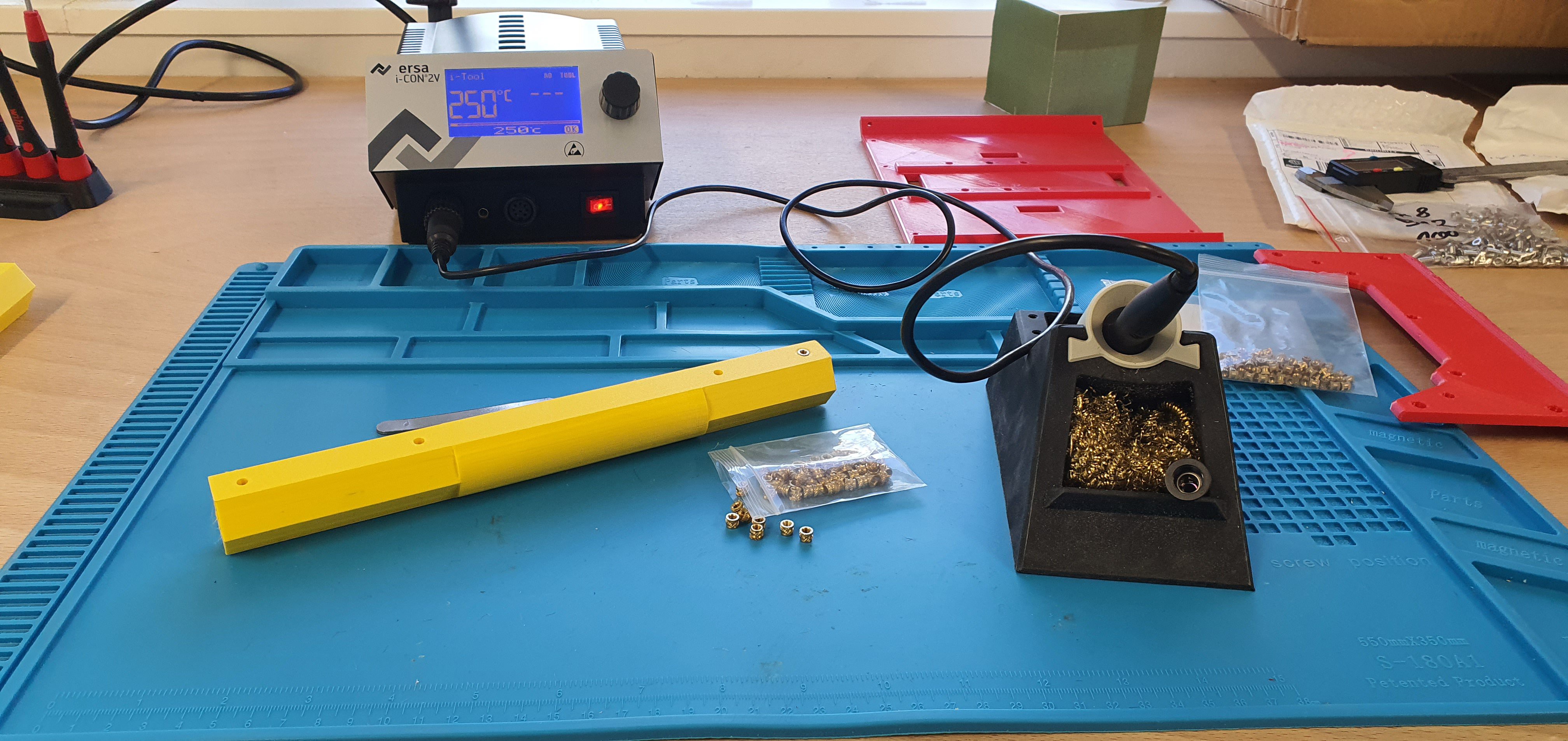
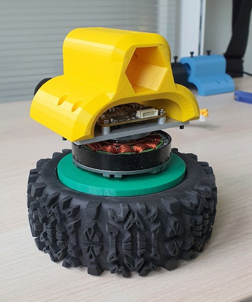
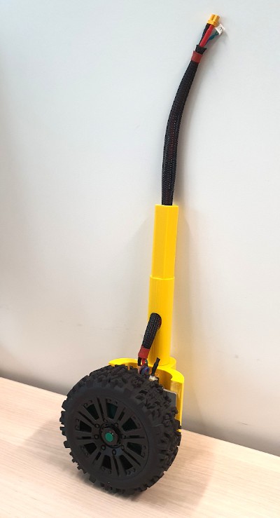
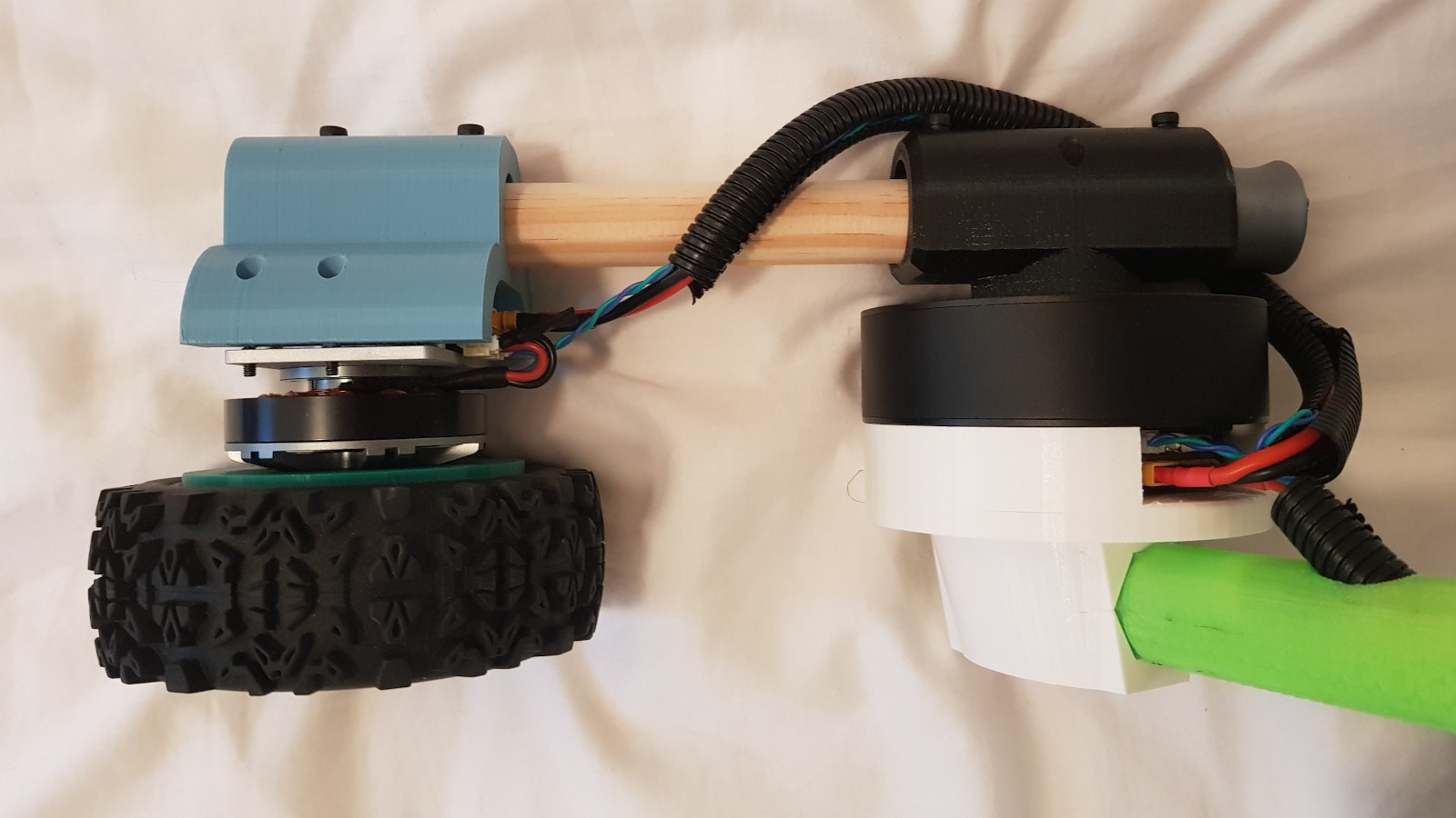
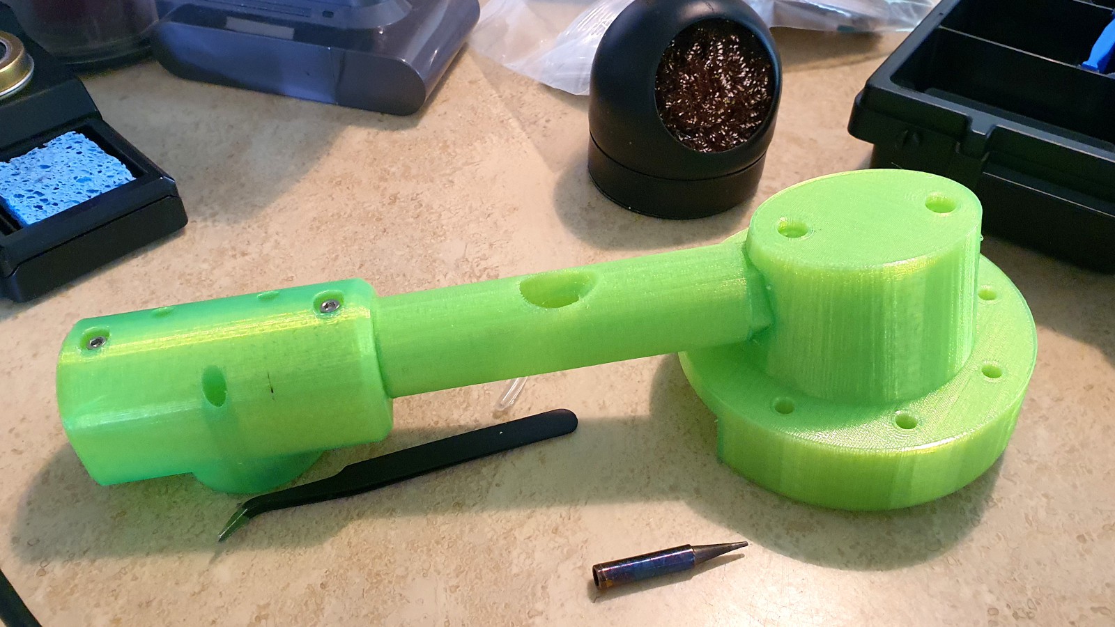
To build a new Upkie from scratch, expect to spend around $3,000 in components, 60+ hours in 3D printing, and more hours of your work assembling and testing the beast. Check out the step-by-step build instructions for details, and head over to GitHub for community support on both hardware and software.
0%
0%
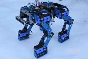
Upkie wheeled biped robots
Wheeled biped robots that can balance, go around and more. Upkies are fully open source, both hardware and software.
Become a Hackaday.io member
Already have an account? Log in.
Just one more thing
To make the experience fit your profile, pick a username and tell us what interests you.
Pick an awesome username
hackaday.io/
Your profile's URL: hackaday.io/username. Max 25 alphanumeric characters.
Pick a few interests
Projects that share your interests
People that share your interests


 Dimitris Xydas
 Kevin Harrington
 Loukas K.
 jdelbe
hello,Can it achieve biped walking in the future?