 land-boards.com
Why Use Hardware Handshake?
I really need hardware handshake to work. Older Retro-computers running BASIC just don't support transferring data without some throttling.
Other Throttling Techniques
There's a number of other throttling techniques that could be used. In fact, one of the other methods would have to be used for a target system that does not have a hardware handshake line.
One method is to add delays after each character or each line.
For some targets setting the baud rate slow enough may work. 300 or 1200 baud works with many legacy systems. These systems were used with cassette tapes and they had to "keep up" because there is no hardware throttling.
Another method for some targets could be to wait for a character to be echoed back. For instance, on MIKBUG systems echo is an option that can be turned on. This effectively ensures the target got the character. It also cuts throughput in half.
A combination of any of these should match most Target systems. All of these could easily be built into the code and configured through the serial configuration menu.
My Target Application
My target application is to transfer data to/from the slowest Target System I have, the Multicomp Build of the UK101. The Serial interface is on J5 in the upper right of this picture. It is shown hooked up to an FTDI card.
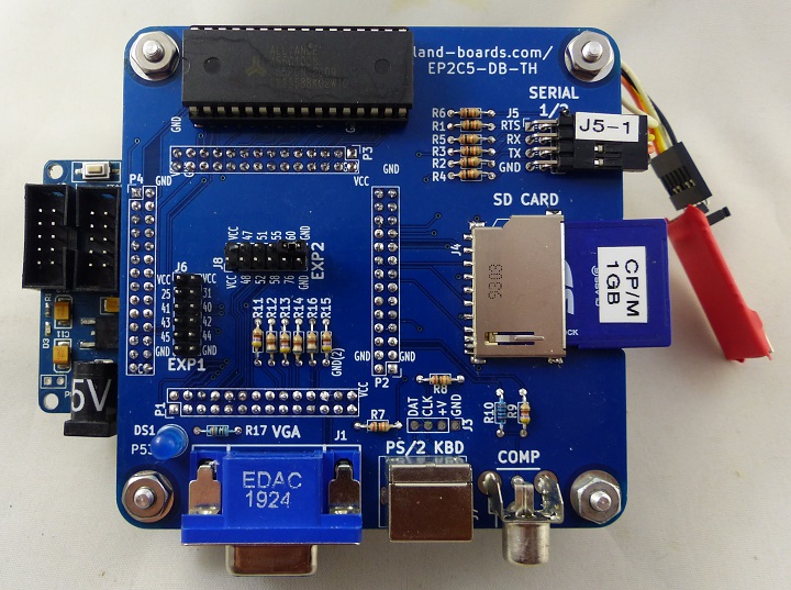
The design is a 6502 running at 1 MHz in an FPGA. The UART in the FPGA supports RTS/CTS handshake. Technically, it only has 1 handshake out of the card but I could add an I/O line for the handshake in. The UK101 currently assumes that the Host can receive data without throttling. That itself could be an issue for saving files to the SD card, but I'm ignoring that issue for now.
If the Multicomp UK101 is ready to receive data is pulls the RTS output pin low. If the UART is "full" it pulls the line high. This tells the Host to pause or resume sending serial data into the card.
Ideally, I'd like to run at 115,200 baud with full handshakes in both directions. I'd like the SD Loader to pause sending data if the Target signals that it is not yet ready to receive data and be able to signal the target that the SD Loader is able to receive more data. There's enough pins on J5 since only one half of the 2x4 header is used. The other RTS pin could be used as a CTS signal.
The UART in the target system is a 6850 in VHDL. It supports Hardware Handshake in both directions.
Technical Excursus
None of this is traditional RTS/CTS usage. The meaning of the term has changed over the years since the RS-232 spec was written originally. Another helpful write up is here. There's a good write-up of this subject here. This ties into the question of DCE vs DTE.
Let's just ignore all of this for now and just call the RTS signal the line from the Target System that signals it is ready to receive data. CTS will be the signal from the SD Loader to the target that it is ready to receive data. Both are active low signals. Data can be sent when the line is low and should be not sent when the line is high.
Having Trouble
I'm having a rough time getting Hardware Handshake working in CircuitPython. There's some indication in some of the documents that hardware handshake should work but I'm getting errors when doing the pin assignments.
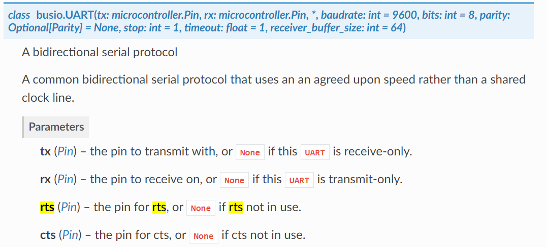
The CircuitPython UART reference page shows that the busio.UART constructor supports RTS and CTS as the following:
    elif baudRate == baud9600:
        if handShake == NoHandshake:
            uart = busio.UART(board.TX, board.RX, baudrate=9600)
        elif handShake == HWHandshake:
            uart = busio.UART(board.TX, board.RX, rts=board.A2, cts=board.A3, baudrate=9600)
The error message is:
Traceback (most recent call last):
  File "", line 724, in
  File "", line 679, in loadConfig
  File "", line 534, in setUARTConfig
ValueError: Invalid pins
Line 534 is the last line, ie:
uart = busio.UART(board.TX, board.RX, rts=board.A2, cts=board.A3, baudrate=9600)
I've tried various pin assignments for the RTS, CTS pins (D2, A2) without success.
uart = busio.UART(board.TX, board.RX, rts=board.D2, cts=board.D3, baudrate=9600)
Not sure if the cts, rts is just not supported in this CircuitPython. I can't find any examples on the web of using these pins.
Manual Workaround
Put in a "manual" workaround to make the RTS/CTS digital Input / output lines and stop sending out data if the line from the other end signals it's not ready for more data. I really hate to have to do this "manually" but feel stuck. If the problem is in CircuitPython perhaps it will be working in there.
Pin Usage
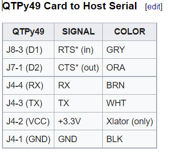
Added Pin Initialization Code
# RTSin is the signal from the target that it is ready to receive data
RTSin = DigitalInOut(board.D1)
RTSin.direction = Direction.INPUT
RTSin.pull = Pull.DOWN  # Enable out if wire is not connected

# CTSout is the signal from the SD Loader that it is ready to receive data
CTSout = DigitalInOut(board.D2)
CTSout.direction = Direction.OUTPUT
CTSout.value = False  # Active low
Updated Serial out code
# uploadSerial() - Upload the selected file on the serial port
def uploadSerial():
    global selectedFile
    pathFileName = selectedFile[0] + selectedFile[1]
    if serialDebug:
        print("uploadSerial(): listing file",pathFileName)
    # Make sure file was selected first
    if pathFileName == '':
        errorMessage("Select file first")
        return
    # Make sure baud rate was selected
    if baudRate == baudUnconfig:
        errorMessage("Config baud rate!")
        return
    clearOLED(display)
    printToOLED(display,0,0,"Uploading Serial")
    printToOLED(display,0,1,pathFileName)
    updateOLEDDisplay()
    sendFileOutSerial(pathFileName)
    printToOLED(display,0,2,"Upload is Done!")
    updateOLEDDisplay()
    time.sleep(2)
    return
Tested by pulling the handshake up/down. Works good. Not sure how large the output buffer is. Setting the baud rate to 300 and pulling the line high/low shows several "lines" of data get sent out before it stops. This could over-run the receiver on the UART.
From the UART reference documents, it looks as if the input buffer size could be set but not the output buffer size.
classbusio.UART(tx: microcontroller.Pin,
rx: microcontroller.Pin, *, baudrate: int = 9600,
bits: int = 8, parity: Optional[Parity] = None,
stop: int = 1, timeout: float = 1,
receiver_buffer_size: int = 64)
It might be necessary to write a low-level driver to control the UART directly to really do this right.
Discussions
Become a Hackaday.io Member
Create an account to leave a comment. Already have an account? Log In.