 Peter Riccardi
Introduction
Acousticians and acoustical engineers often rely on laboratory grade measurement microphones to acquire physical signals during experiments. Typical condenser microphones from companies such as PCB PIEZOTRONICS could run a bill of over $1000 USD for a free-field microphone. The quality of such microphones is superb, but there are alternatives available to the hobbyist and enthusiast which will get you comparable performance for a fraction of the cost. Here, a MEMs based design is explored with the ultimate goal of having a similar noise floor, frequency response, flatness, and sensitivity in the audio band of 20Hz to 20kHz.
Electrical Design
The electronics is split into two boards for the prototype. Ultimately, this should be done with a rigid-flex design to aid in the assembly of the microphones. However, two boards with point-to-point wiring is fine for the prototype and proof of concept. The first board is the MEMs carrier board. Four MEMs elements are mounted on a circular PCB with small through-hole pads scattered around for the necessary power and signal connections.
The second board is the Motherboard or the preamplifier. This contains the inputs and signal conditioning for the MEMs outputs, as well as the IEPE conversion and output modulation - all done with adjustable Zener diodes.

Figure 001: Schematic print of the motherboard/preamplifier board. The jumpers are simple through-hole pads that will accept the wire connections for the BNC interface (brings in IEPE power and outputs the signal) and to connect the carrier board to the preamplifier (signal and power from the four MEMs).
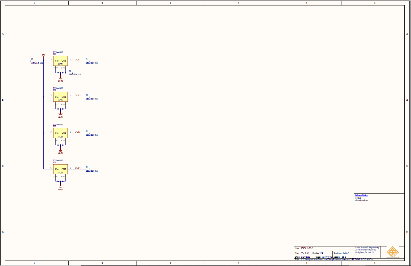
Figure 002: Schematic print of the carrier board. The carrier board consists of four MEMs elements and jumpers (through-hole pads) to provide an interface for power and signal on the board.
Why Four MEMs Elements?
Electrical noise, well any noise for that matter, is a complicated phenomena. It would take far too long to discuss noise at length, but the basics will be discussed here. For electrical systems, any passive and active component that has a voltage drop across it will produce some form of noise. Here, it is assumed that active components will have a broadband white noise signal from which the output signal rides on. Since noise is inherently random, and therefore completely uncorrelated, the output noise from active electronics can be averaged out. Board layout, and other forms of coupling make this not exactly true - but to a first order approximation it works. By tying the outputs of multiple noise sources together in parallel (via small valued resistors) the output noise floor has an overall reduction which therefore increases the signal to noise ratio. Condenser microphones have excellent signal to noise ratios with typical sensitivities being on the order of 50mV/Pa. By using four MEMs elements in parallel, the overall signal to noise ratio is improved at minimal effort and cost.
IEPE
IEPE is a type of two wire interface for measurement and DAQ systems which outputs a constant current into the load via the positive and negative (two wire) nodes. Typical current values range from 2-20mA, NI devices being on the low-end of that spectrum at 2.1mA of excitation. IEPE works on the principal that since constant current sources can operate into a wide range of operating voltages (the compliance voltage) the sensor can modulate the compliance voltage with output signal and the excitation current will still flow downstream into the sensor to power the device. Typical compliance voltage maximums exceed 20VDC and typical operating points are in the 10-15VDC range. The circuit here is designed to operate at the bottom of the current range (2.1mA) and has an operating point (compliance voltage) of around 13VDC.
The adjustable Zener diode U2 along with the resistor R3 set the power rail for the active electronics. This Zener needs enough cathode current to remain stable while it powers the four MEMs and the four low power operational...
Read more »


 Clyne
Clyne
 Ghani Lawal
 Arno
Arno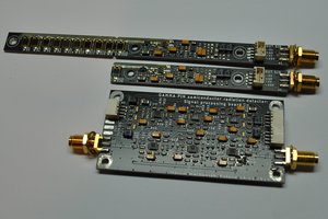
Inspiring. I'm working on an air traffic decibel monitoring project where a units consisting of a mems module (PCB Artists) and a Raspberry Pi Zero 2W log decibels. The hardest point is to design a microphone for outdoor use 24/7. Weather/rodent/pest/dust proofing is going to be a hurdle. Thank you for posting and sharing your excellent work product.