Intro
Our group had a 10-week period to create Dum-E, so we had to be clear on what was important to the project in order to finish the project in this time. Dum-E’s software side consisted of setting up a web server, creating an appealing user interface, and implementing a detection algorithm on the server side. Dum-E’s hardware side consisted of implementing proper motor control logic, picking out proper components so that all the electronics could be run off one power supply, and creating a PCB to organize these electronics in a neat and compact manner. Dum-E also consists of a custom pan-tilt enclosure in order to fit the chosen electronics and provide satisfactory camera placement.
One of the main goals we had in mind when coming up with an idea for this project is doing something that both spans multiple disciplines and aligns with today’s technological trend. For example, we wanted to incorporate some degree of advanced data processing, whether that be machine learning or computer vision. Building on top of the server requirements, we wanted to explore wireless architecture employed in today’s industries.
Ultimately, this led to this project, which seems to meet the aforementioned requirements and is also doable in 10 weeks. The project would incorporate some degree of automation and computer vision, has a good degree of interactions with the physical world (through the use of cameras and motors), and also require some understanding of network protocols to support multiple video streams.
While building a fully functioning product is ideally what we hope to achieve by the end of this quarter, the biggest takeaway we hope to gain from this project is understanding the technical details and design process involved in building these electronic embedded systems, such as networking, software principals, hardware designs, and electronics.
System Overview
Our system can be broken up into three major areas: (1) software, (2) electrical hardware, and (3) 3D-printed enclosure. The core logic and flow of our system are best characterized by the block diagram shown in Figure A below.
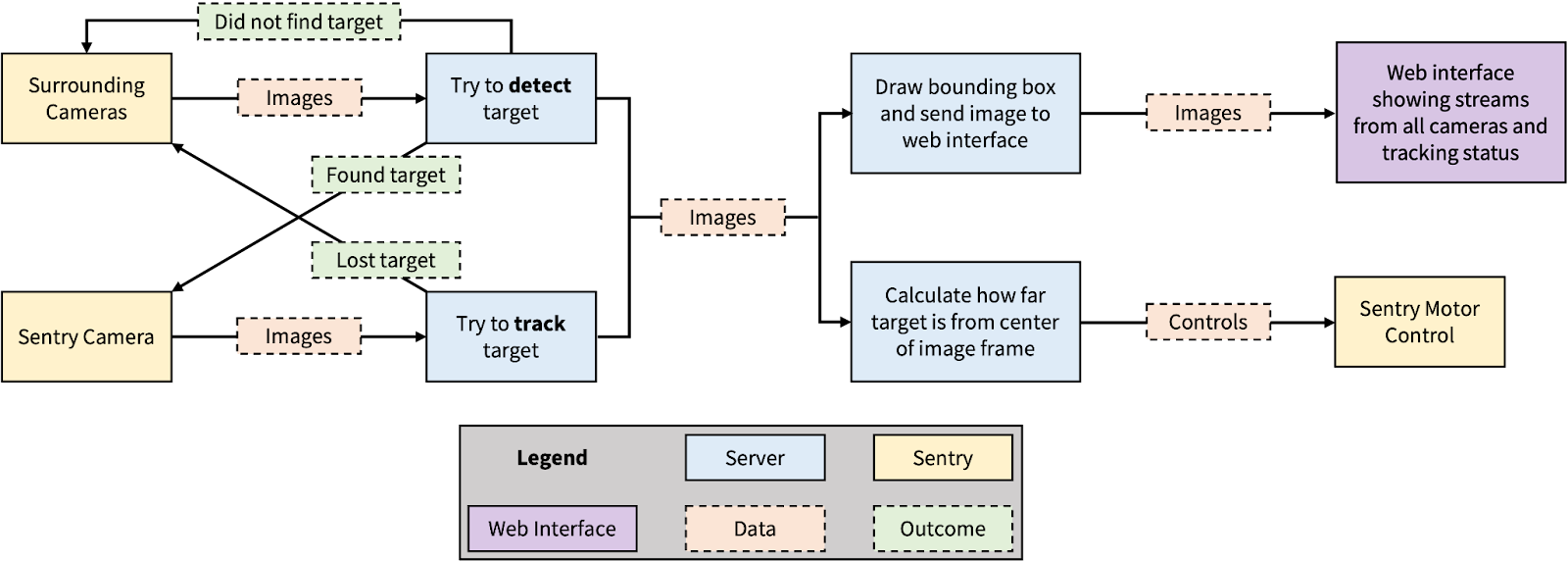
Figure A: Block Diagram
The specifics of the listed areas and parts are further elaborated in the following sections.
Software
The software can be further divided into three categories: (1) the central server and (2) the Arduino programs that run on the edge devices, and (3) the web interface. The interaction between these categories is shown in Figure B. The central server corresponds to device 2, edge devices (specifically ESP-32s) to device 3 and 4, and the web interface to device 1. The green arrows represent the flow of data between devices.
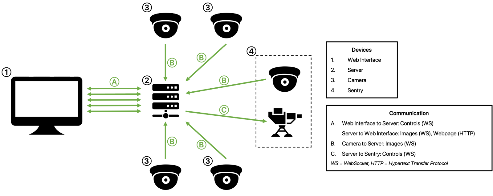
Figure B: Software Architecture
Central Server
The sentry can operate in two modes, automatic and manual, both of which can be set through a web interface. In manual mode, the user can control the sentry directly through the web interface, which continuously streams a live-feed from the sentry. In automatic mode, the sentry can be configured to track people or objects.
The central server makes up the blue blocks in Figure A and is the brain of the whole system. All processing—such as image compression, object detection, sentry control—are done on the Python server. As shown in the block diagram and the software architecture above, the server has two main responsibilities: handling the networking details and processing the images. The server is hosted using the Tornado framework and image processing is performed using OpenCV.
Network
Communication between all devices is done through the Tornado framework. The connections between each device can be characterized by the following: (1) the web interface is served via HTTP, (2) the Python server receives live images from all cameras via WebSockets, (3) the web interface sends movement commands to the Python server via WebSocket, and (4) these commands are then forwarded onto the sentry via WebSocket...
Read more »
 Artur Majtczak
 Ulrich