 ElectroBoy
Most of the people working in electronics industry have batteries of different kinds. Because batteries are the only source to make your projects portable. Some of them may Lead acid batteries or lithium-ion batteries. Now these are of different ratings and for every battery we need a separate charger.

To solve this problem, we can make a universal 1.5volt to 12volt battery charger. Output can be selected according to battery ratings through potentiometer. After that we can make a PCB layout and change our circuit idea into a fully functional project.
Components required:
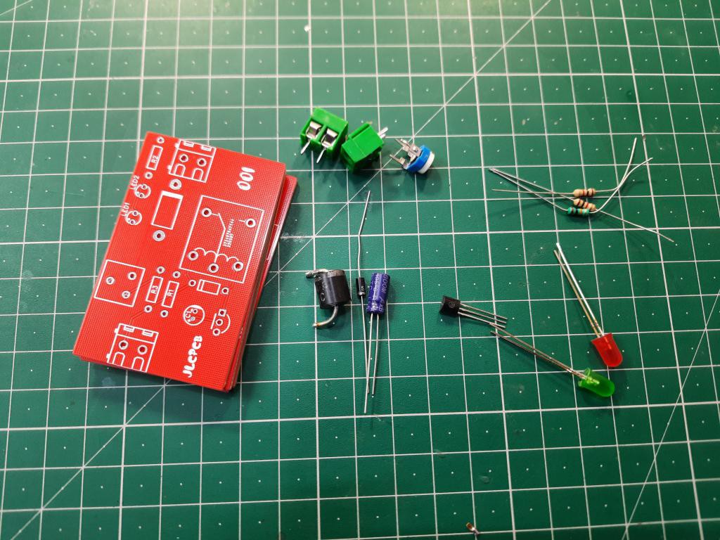
1) 12v Relay
2) 1N4007 diode
3) 220ohms, 1k Resistors
4) Red, green LEDs
5) BC547 transistor
6) 5408 Diode
7) 47uf capacitor
8) 2 screw terminals
9) Custom PCB from JLCPCB
10) 10k potentiometer
Circuit diagram:

Circuit diagram has a potentiometer of 10k with resistor in series and controlling the overall action of relay. Here are some changes in the configuration, you can see the ratings of battery and relay in the diagram given below.
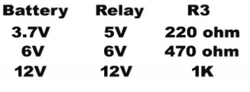
All the other things remains same, just relay and LED protection resistor is changed. Relay coil is always supplied in a parallel reverse baise diode. Which eliminate huge spikes due to voltage across the coil.
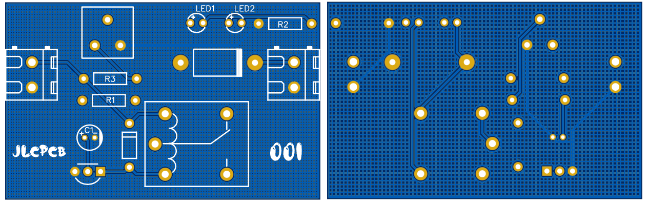
PCB layouts:
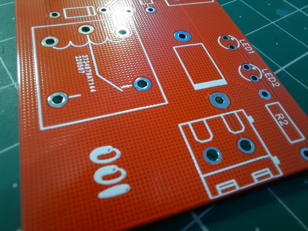
If you want to use the same designs as mine then Download PCB Gerber files from here.
I ordered 1.6mm thick PCBs with Hasl finishing, red solder mask. You can try JLCPCB prototype service for your projects. And here is a good news! If you sign-up using this link you will get free coupons of worth $30 to order PCB and for SMT assembly service. If you want to know more about JLCPCB and SMT assembly service then see our article "Why I prefer JLCPCB for my projects.
Working:

In the above circuit, whole charging is governed by BC547 transistor and relay RL1 acts as the changeover. During charging the circuits takes input via a charger /bridge rectifier charger circuit shown above and through the relay’s COM and NC, the power is directly connected to the battery.

After the battery reaches a certain level the transistor bc547 id tuned ON and it drives a relay which in turn changes the COM pin’s link from NC to NO which is connected to the red colour LED that will start glowing after relay changeover, indicating the battery charging completion.
 Electroniclovers123
 DIY GUY Chris
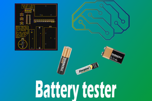
 Adam Redfern
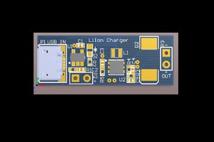
 FrazzledBadger