Antony, BumJoon, Peter
At the start of this project, we were tasked with creating a product using an ESP32 microcontroller and two sensors, with some additional requirements that included wireless communication with a backend server, interfacing with the product via a frontend web application, and more. Because one of our team members tried to retrofit his house with a smart doorbell but found the product to be too complicated to use (and expensive), we decided to build one with all the same major functionalities but cheaper and more user-friendly.
First, we had to outline our project plan. This involved coming up with a list of components we would need for making the doorbell, creating a preliminary design schedule, creating a list of features we would like our doorbell to have, as well as beginning to do some research on how to get the components to wirelessly communicate with each other. Each of these points was addressed in the following presentation:
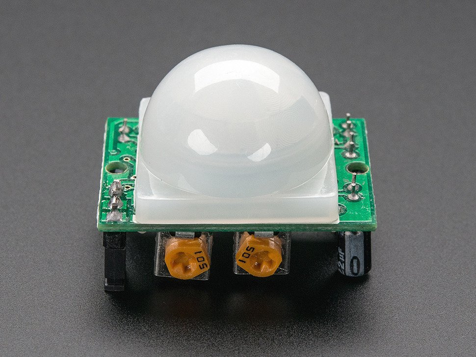
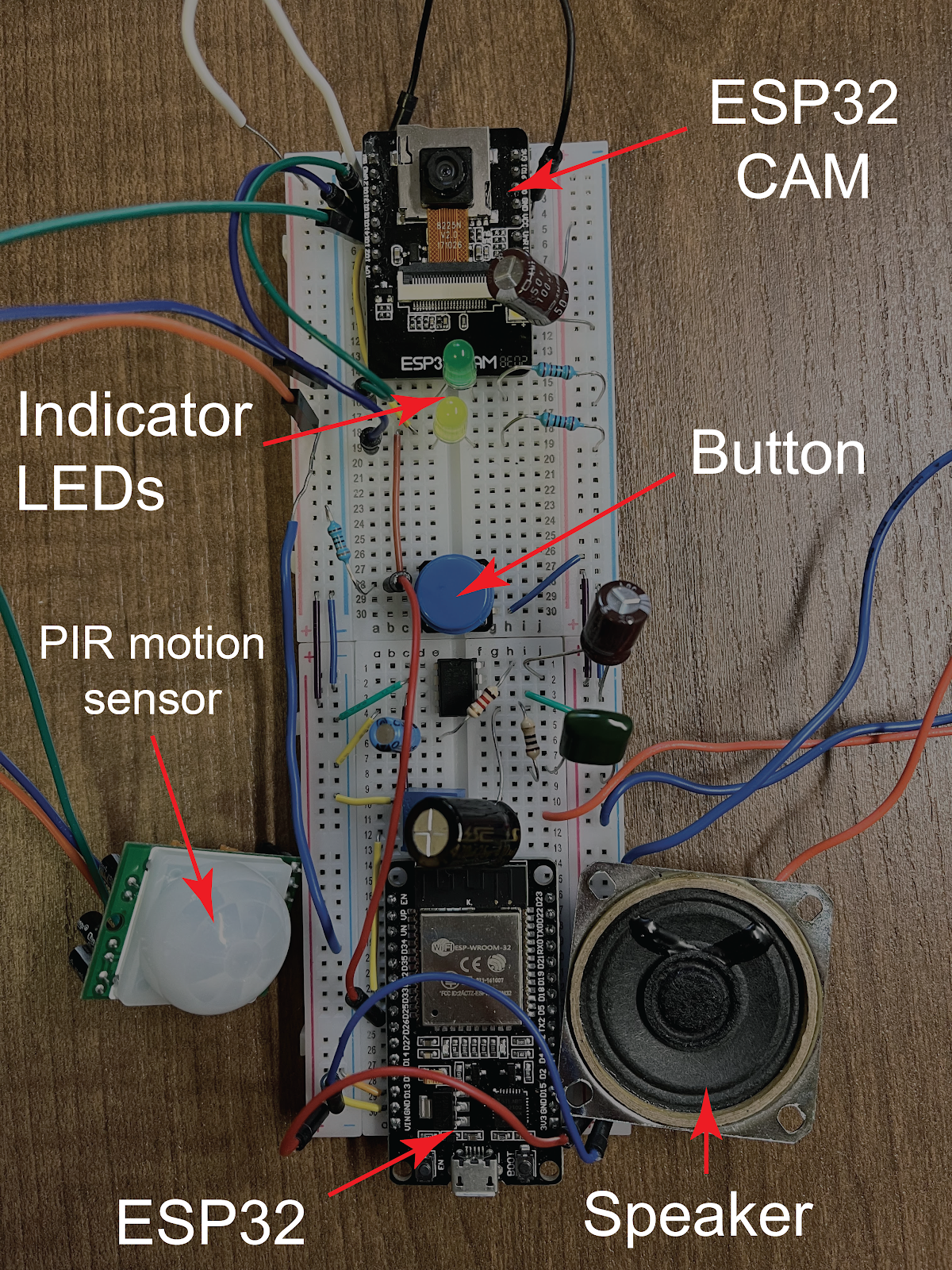
Next up was the initial prototype. We had acquired most of the components we needed, including the ESP32-cam module, a push button, a PIR motion sensor, and more, some of which are pictured below.

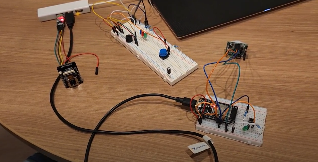
We used these components to build a rough prototype, which interfaced these components together along with a couple of LEDs to display functionality and a USB-connector to provide 5V power to our system. We were able to make it such that pressing the push button lit up one of the LEDs, and the motion sensor being triggered lit up another LED, which demonstrated that we were able to implement some basic functionalities of the components.
From the software side, we had begun setting up a web server using the Tornado server framework in Python. This proved to be a major bottleneck to our progress, as none of our team members had any prior experience working with web servers. After much struggle between looking for tutorials and reading up on documentation, we ended up combining sample code from multiple web server tutorials using Python on the server end and JavaScript on the HTML end. We heavily changed and added features to this sample code to fit our needs, then worked to create a WebSocket connection between our ESP32 cam and our web server.
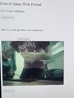
We then took it a step further and created our full prototype. At this point, our WebSocket connection was stable, which meant that we could transfer data from our ESP32 cam to a website hosted by our web server. Then we created a functioning website which we could interface with our existing hardware, which could stream live video at the push of the push button, as well as display the final frame of the video stream via a push of a button on the website. This website was very austere in terms of both the visual aspect and functionality, so we agreed that we would make future improvements to the UI with CSS and add more user features as we polish our design. Our design and website layout are pictured below:
A comprehensive demonstration of our full prototype, as well as our design progress up to this point can be found in the following presentation:
At this point, our team came together to consider improvements for future revisions. Since there were consistently brownouts when working with our hardware, and some problems with the motion sensor that we believed was likely attributed to insufficient power provided, we decided to invest in a 5V power supply to address these issues. We also decided to implement a speaker into our design, which would allow for us to play pre-recorded audio messages in addition to the standard doorbell chime, which was a great additional feature for a smart doorbell. For our website, we decided to implement a log feature that would show timestamps of when visitors approach the doorbell and take a snapshot for viewing, and we also developed some updated graphics and easier user interface for overall better presentation.
After two rounds of revisions and implementing all the features we described, we arrived at our final product. Our physical design as well as our website are pictured below: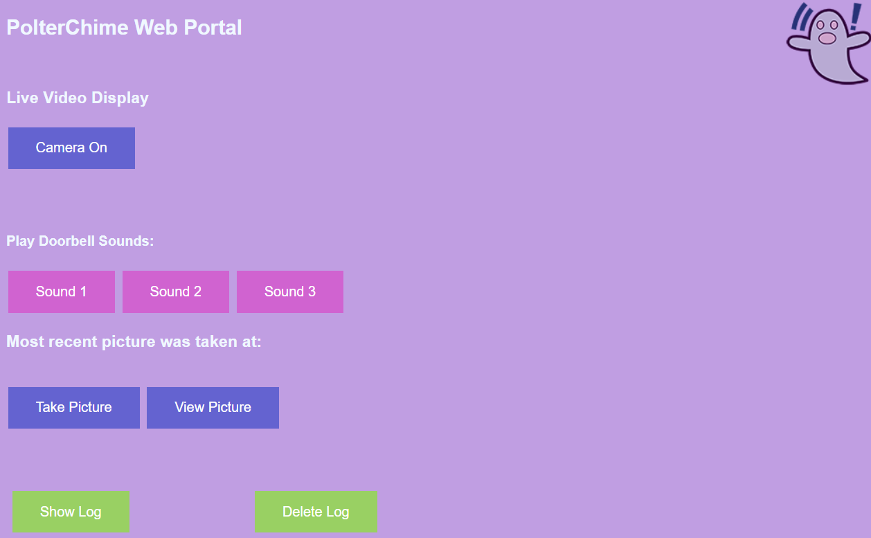
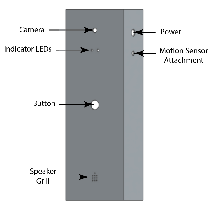
Finally, even though we were unable to physically print it out due to time constraints, we designed a CAD model as mechanical housing for our doorbell. This housing is pictured and labelled below. This housing finishes out the development of a stylish, functional, and easy-to-use smart doorbell.