 kmatch98
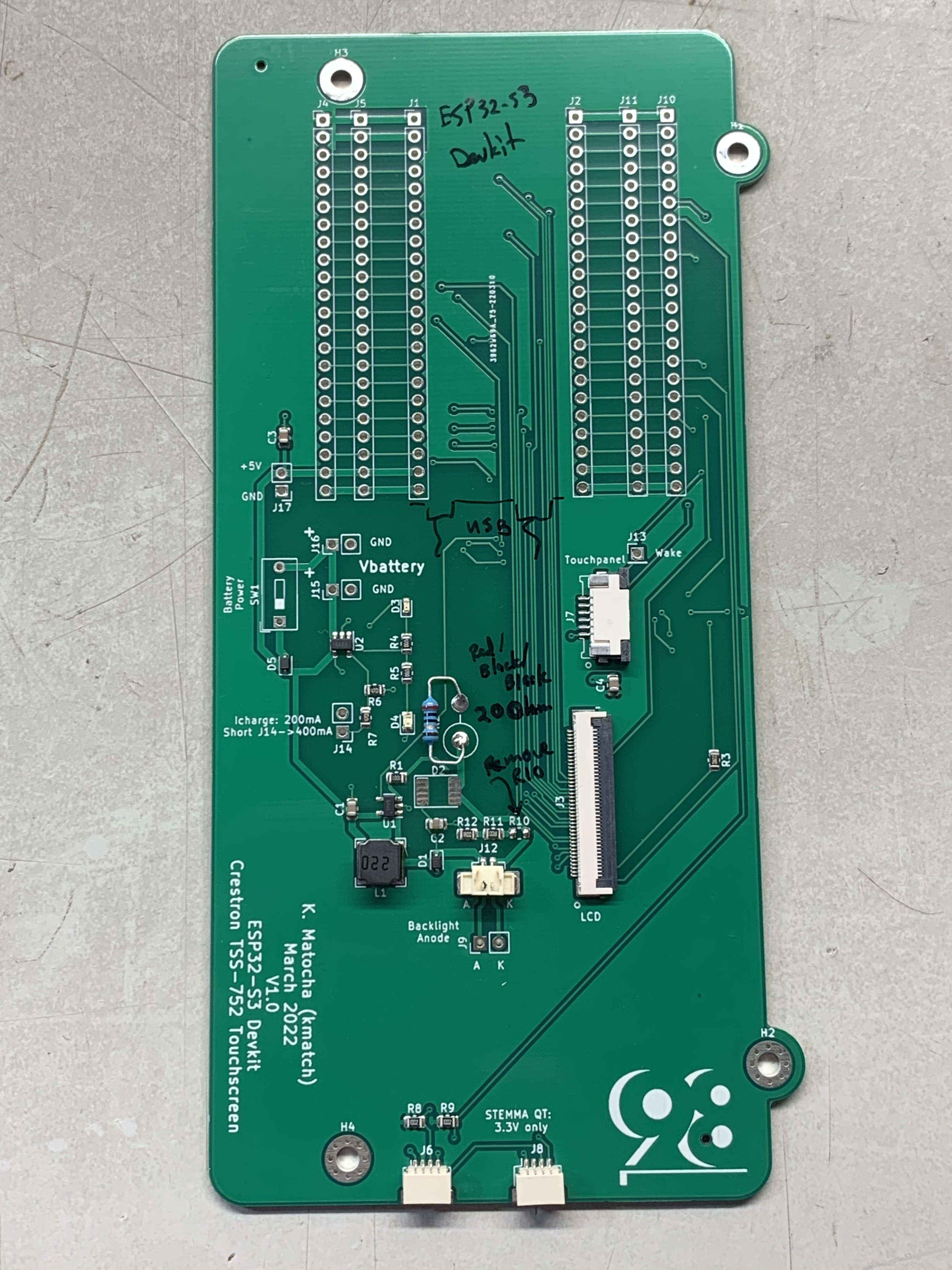
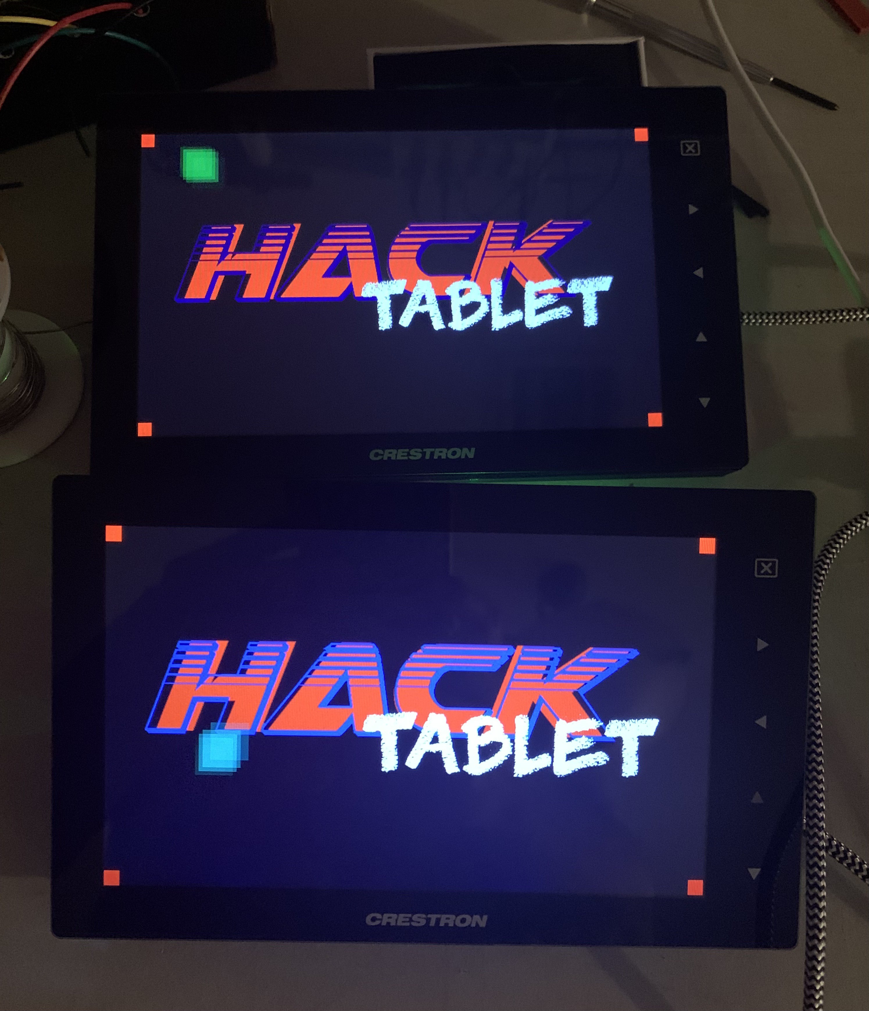
Latest progress on repurposing this display as driven by an ESP32-S3.
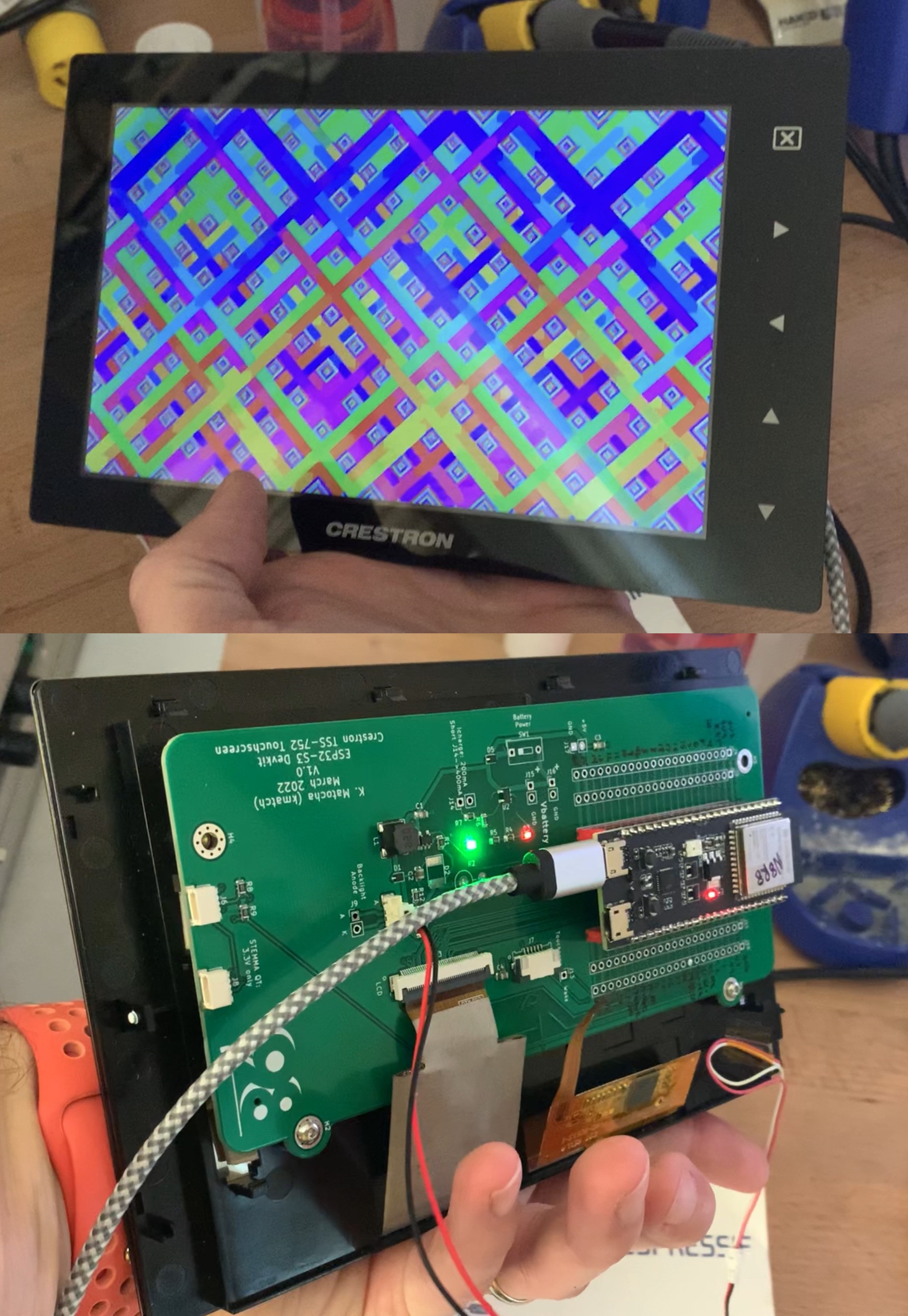
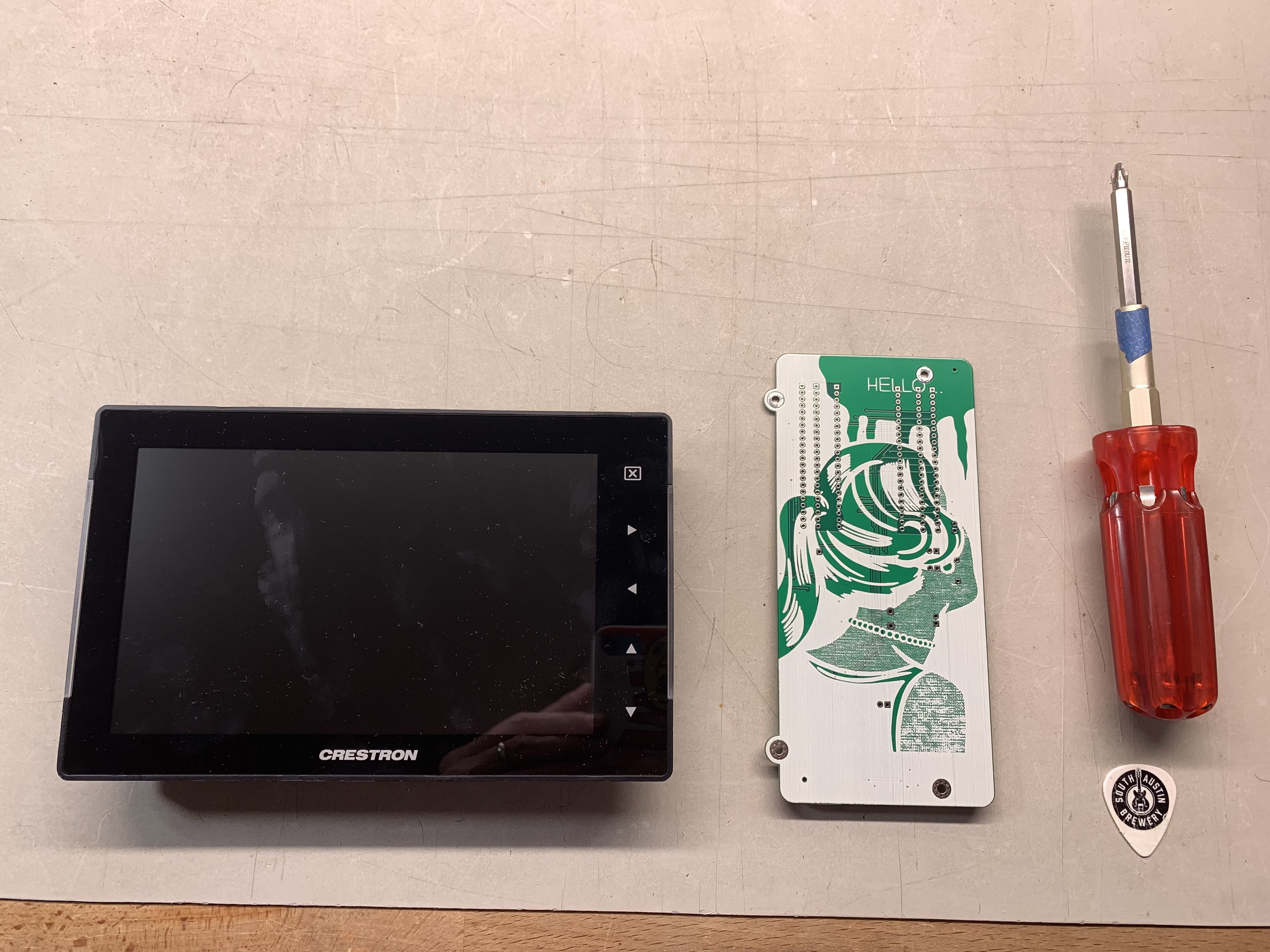
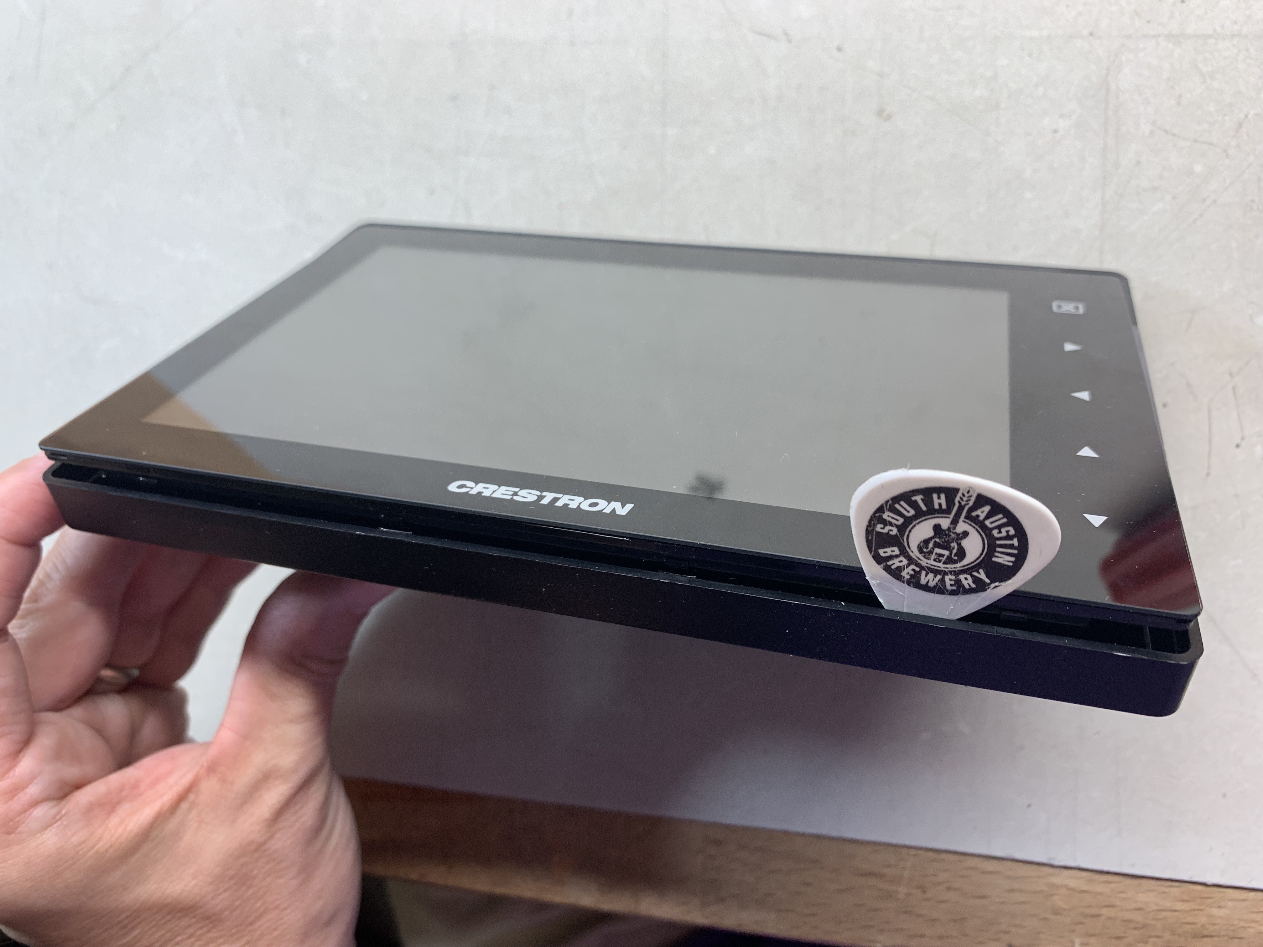
This Crestron TSS-752 appears to be a superior candidate for reuse versus the previous teardown of the Crestron TSW-732.
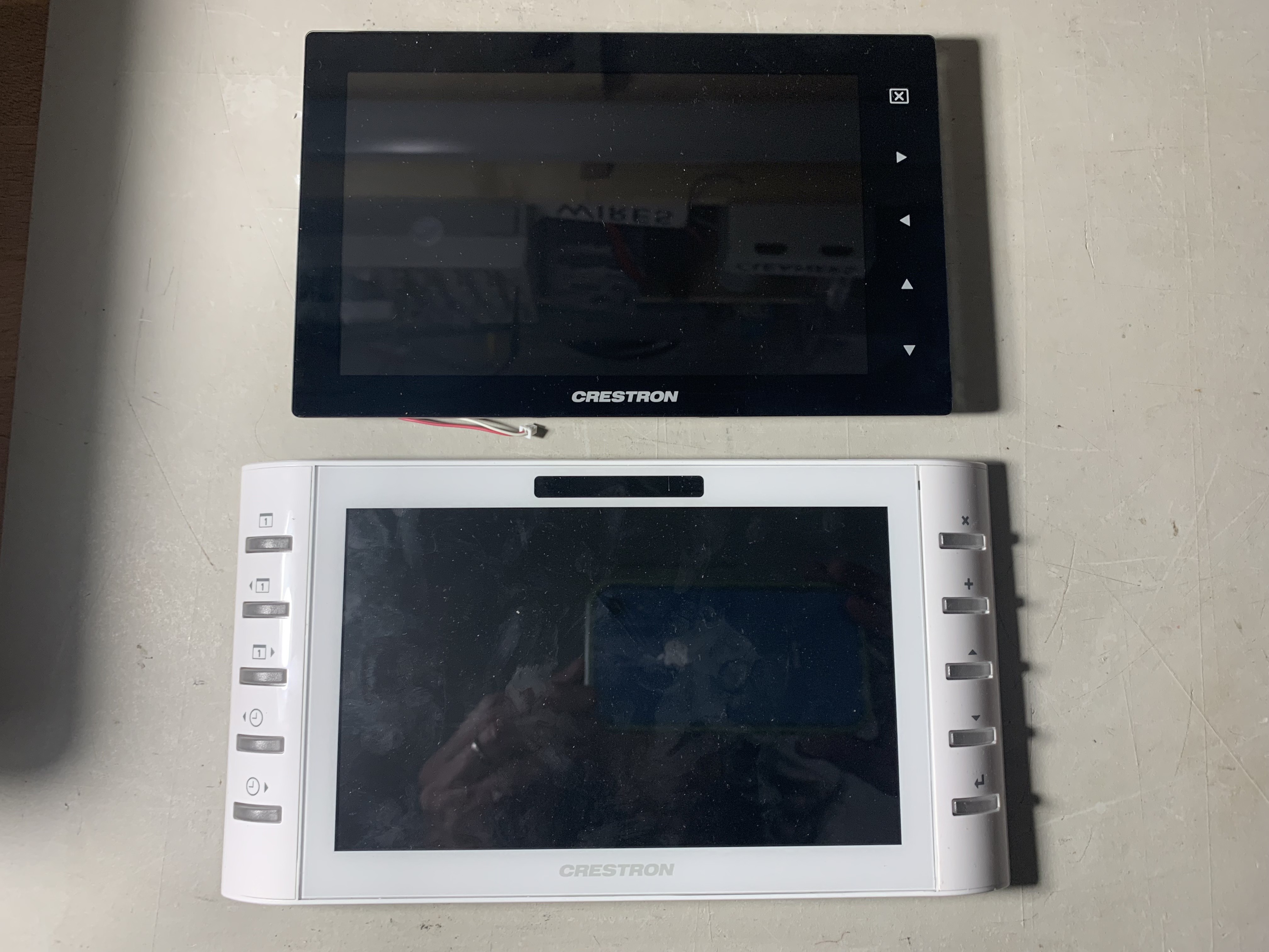
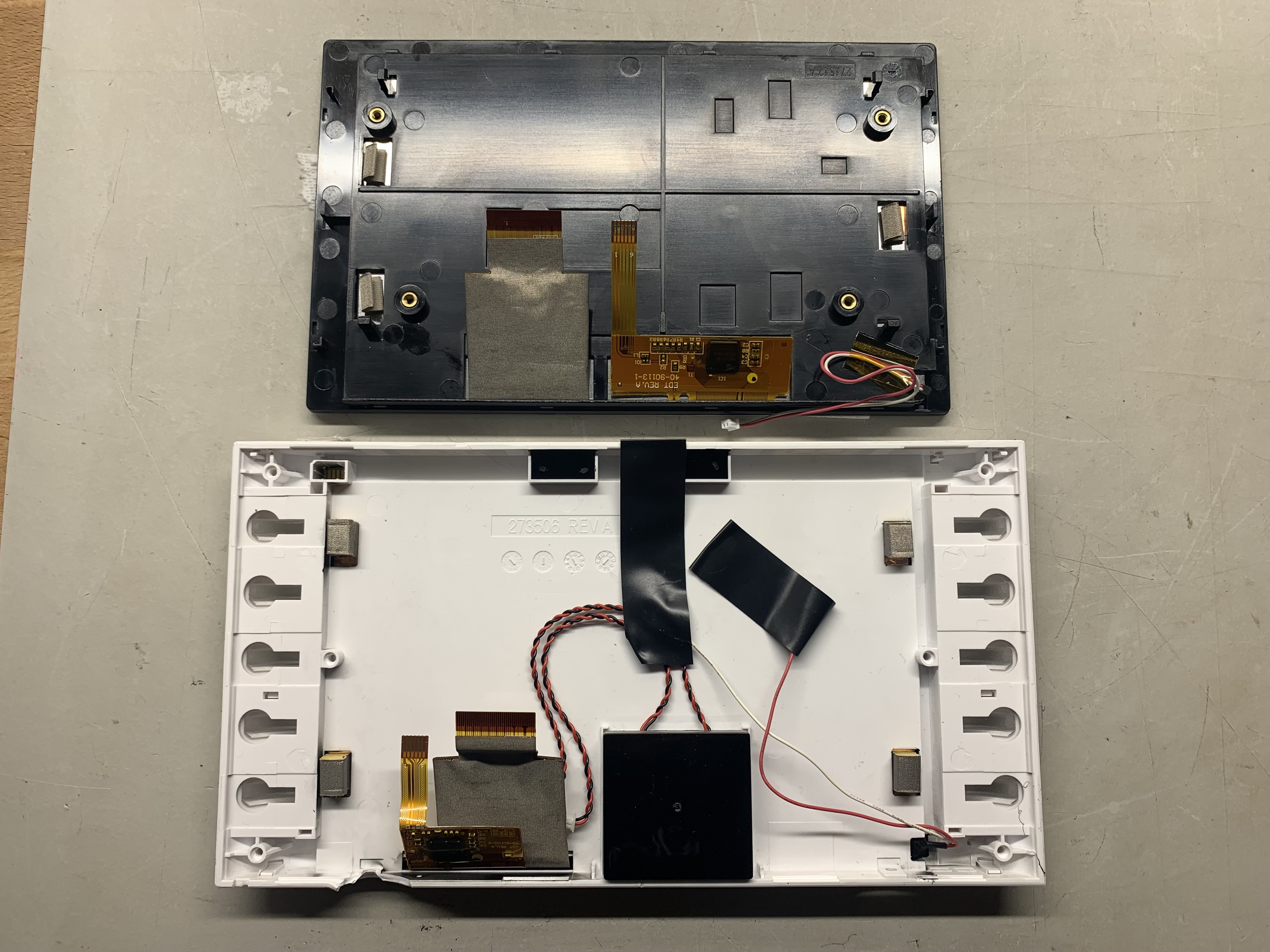
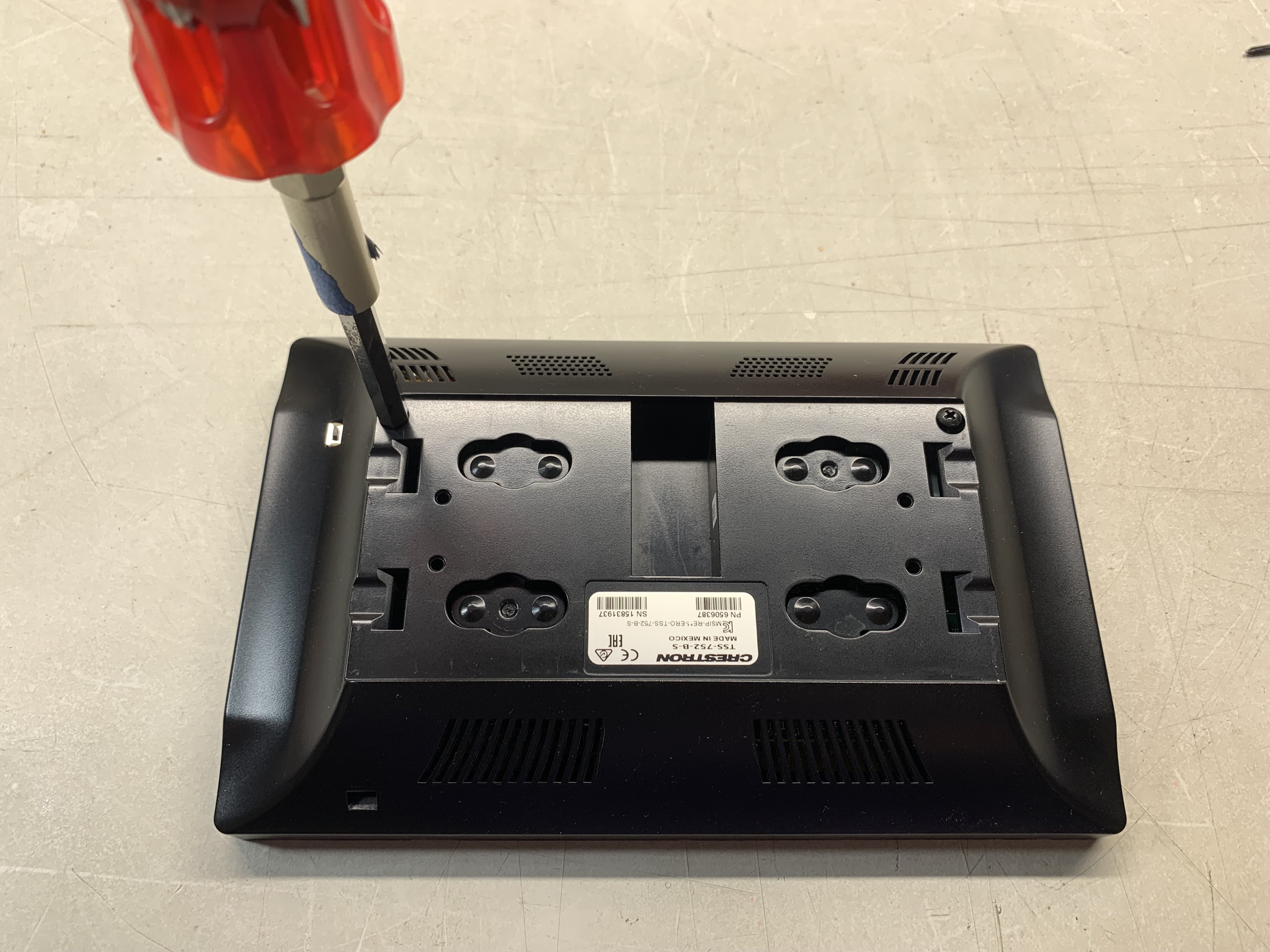
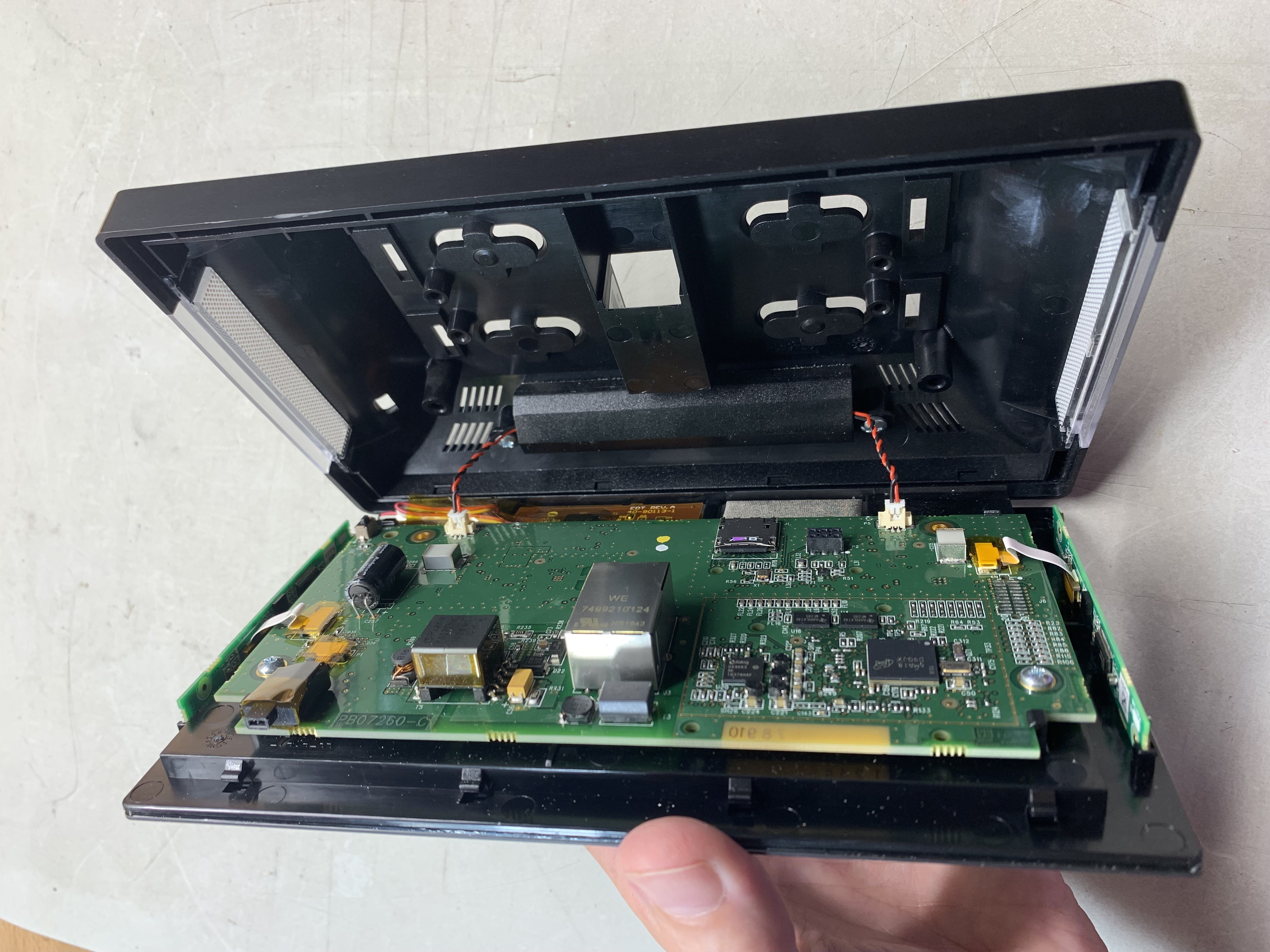
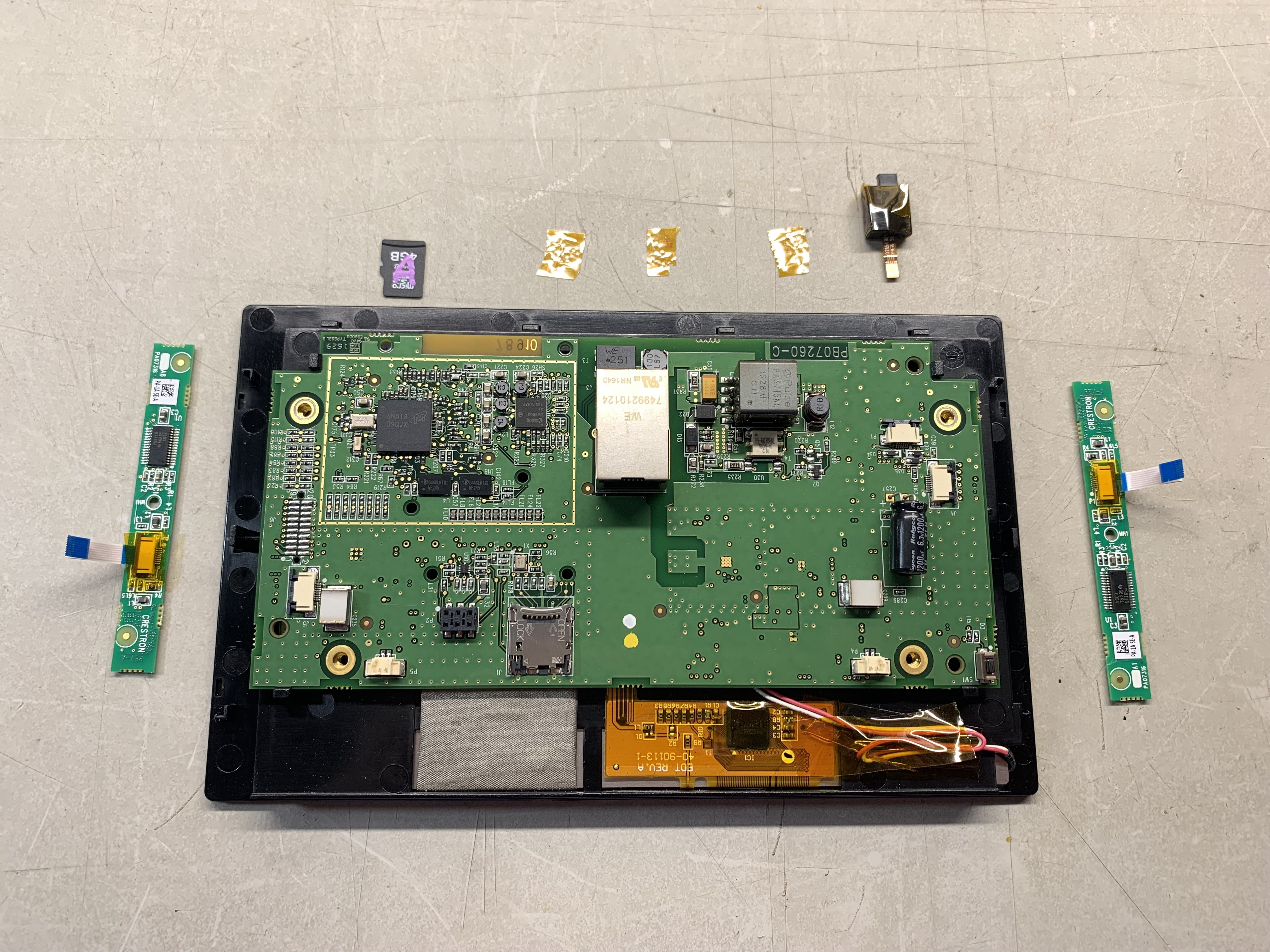
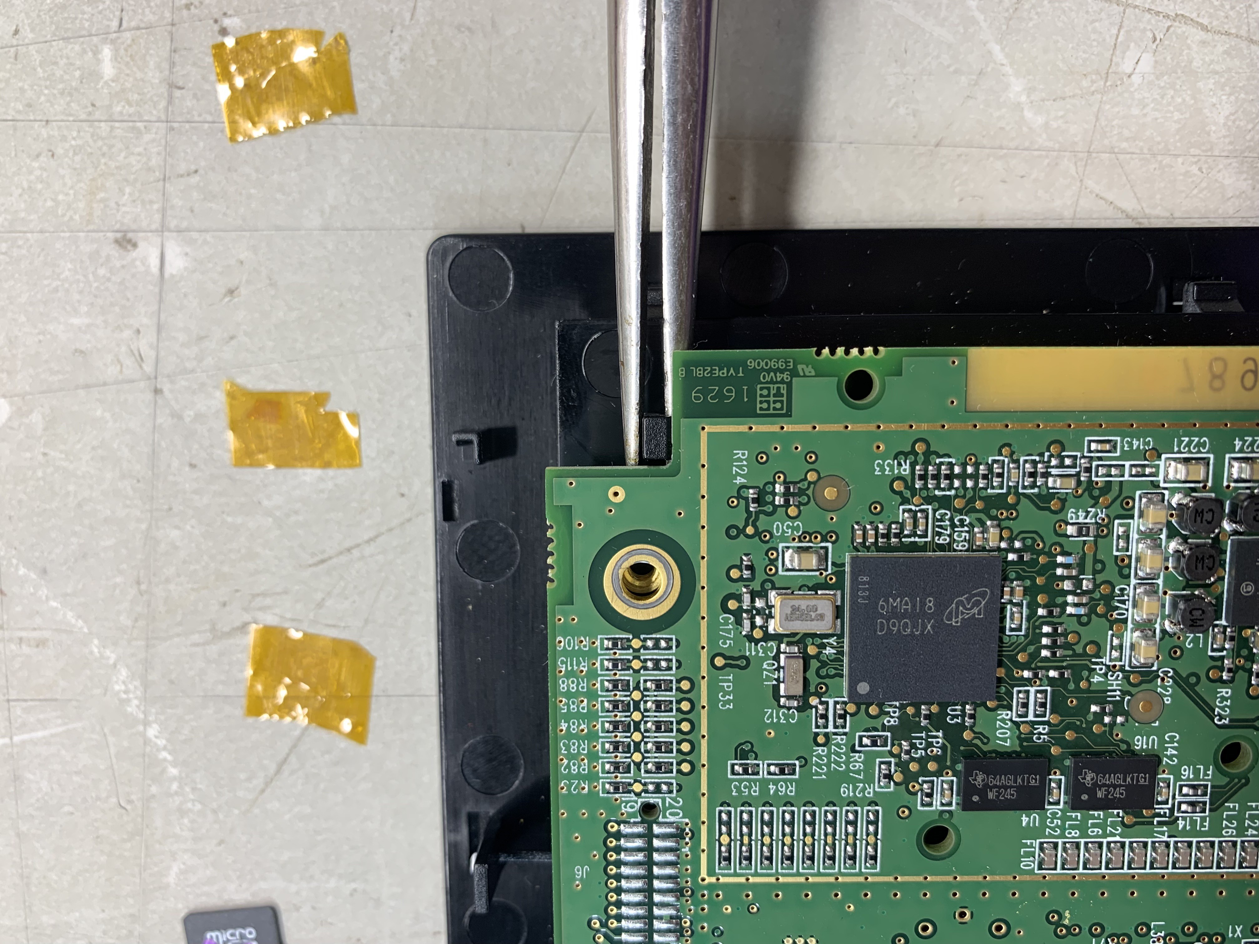
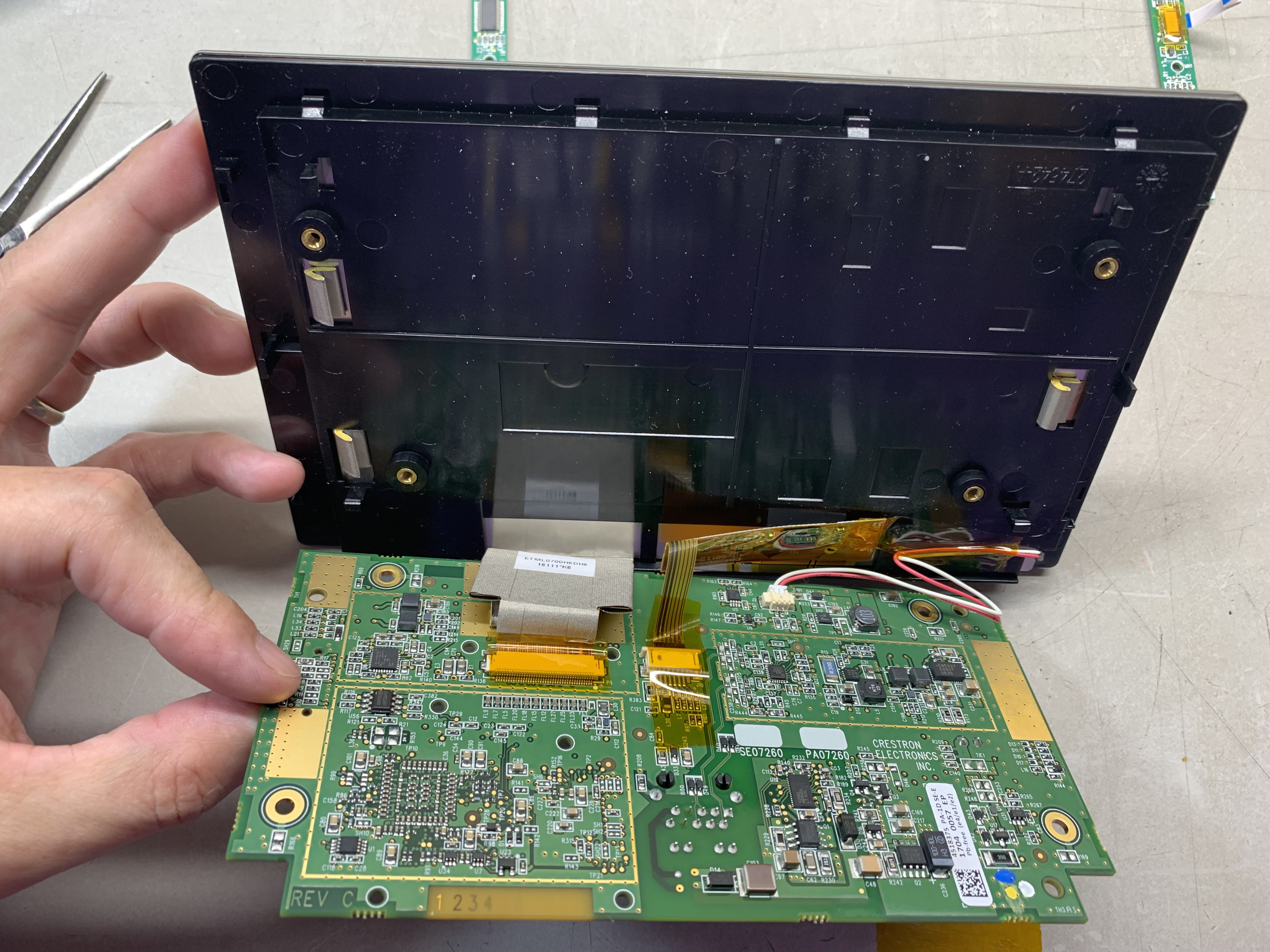
After pulling out the front panels, the TSS-752 is much smaller, since it is not attached to such a large plastic housing. For the white unit, the display is held in the housing with strong adhesive, removing the white unit’s display/touchpanel caused me to damage the panel. In contrast, the black unit’s display comes out after removing two screws, spudgering the other edge out, and springing back four plastic clips.
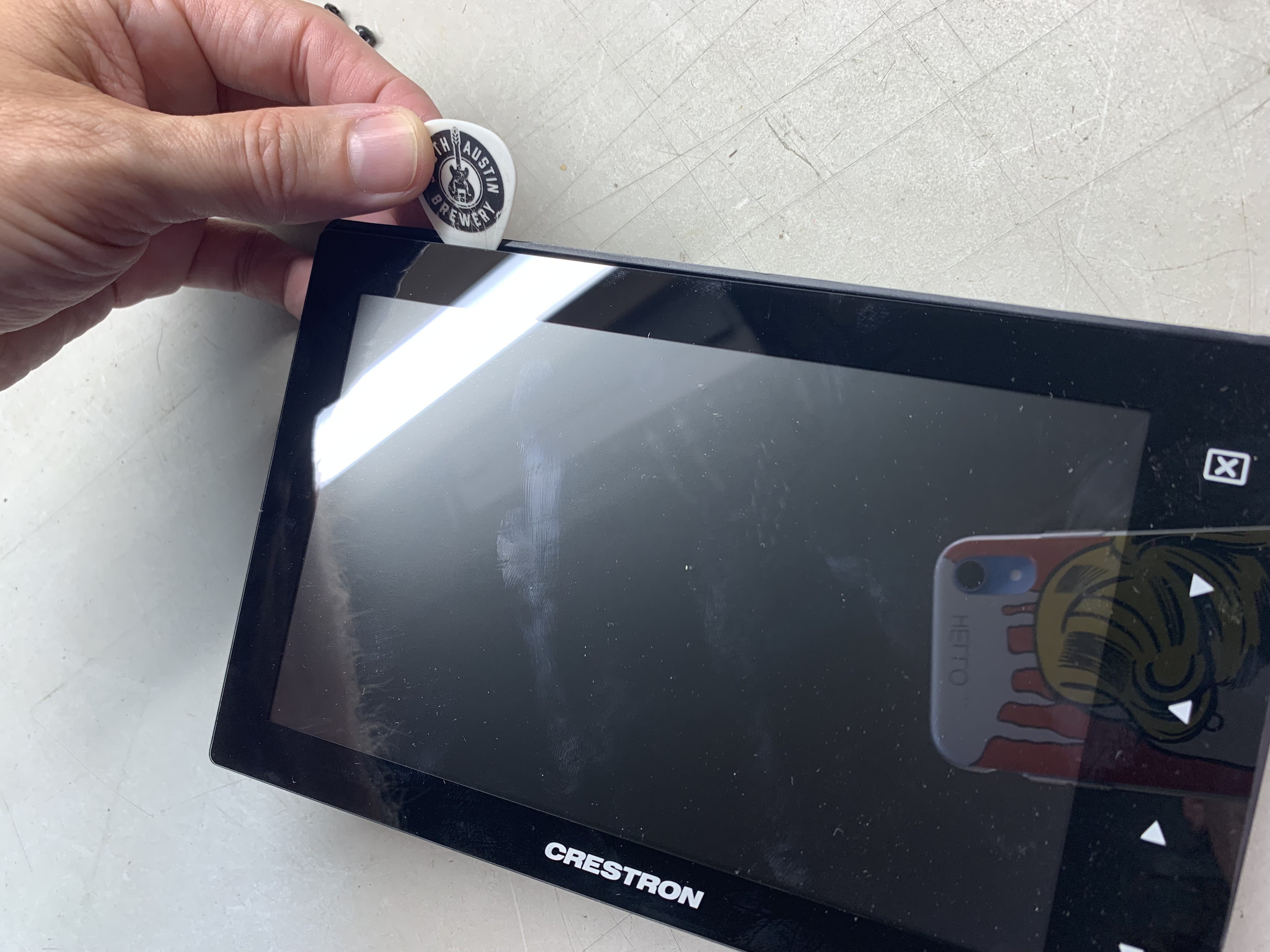
The black unit’s design makes the display more readily accessible and ends up with a smaller footprint. The bezel on both is quite large, though. And the black unit has the additional bezel associated with the touch buttons. Perhaps these buttons are also monitored by the touchscreen, if so that could be useful for something.
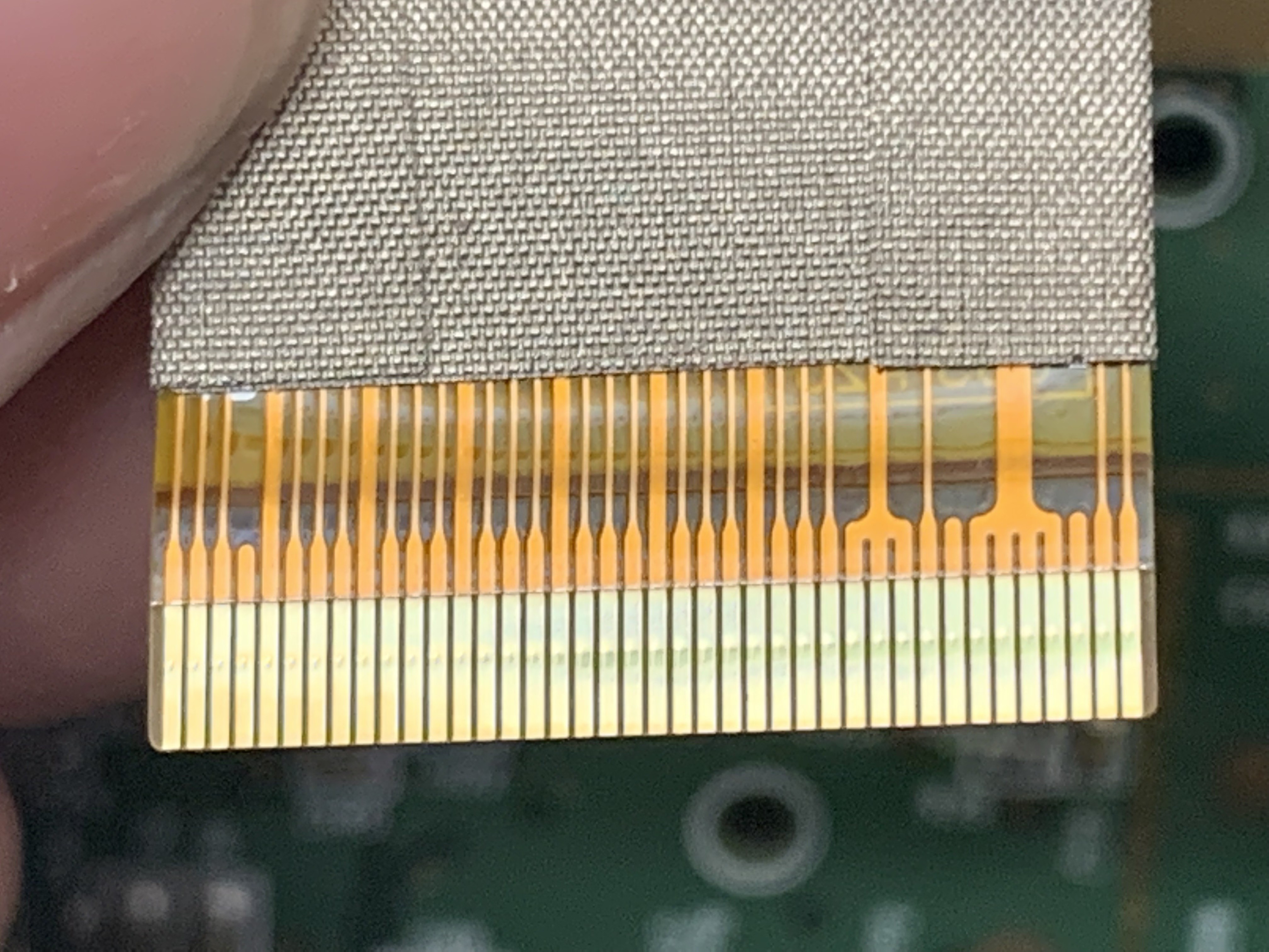
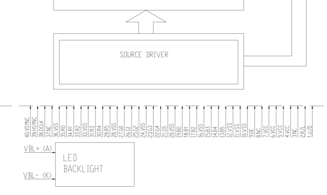
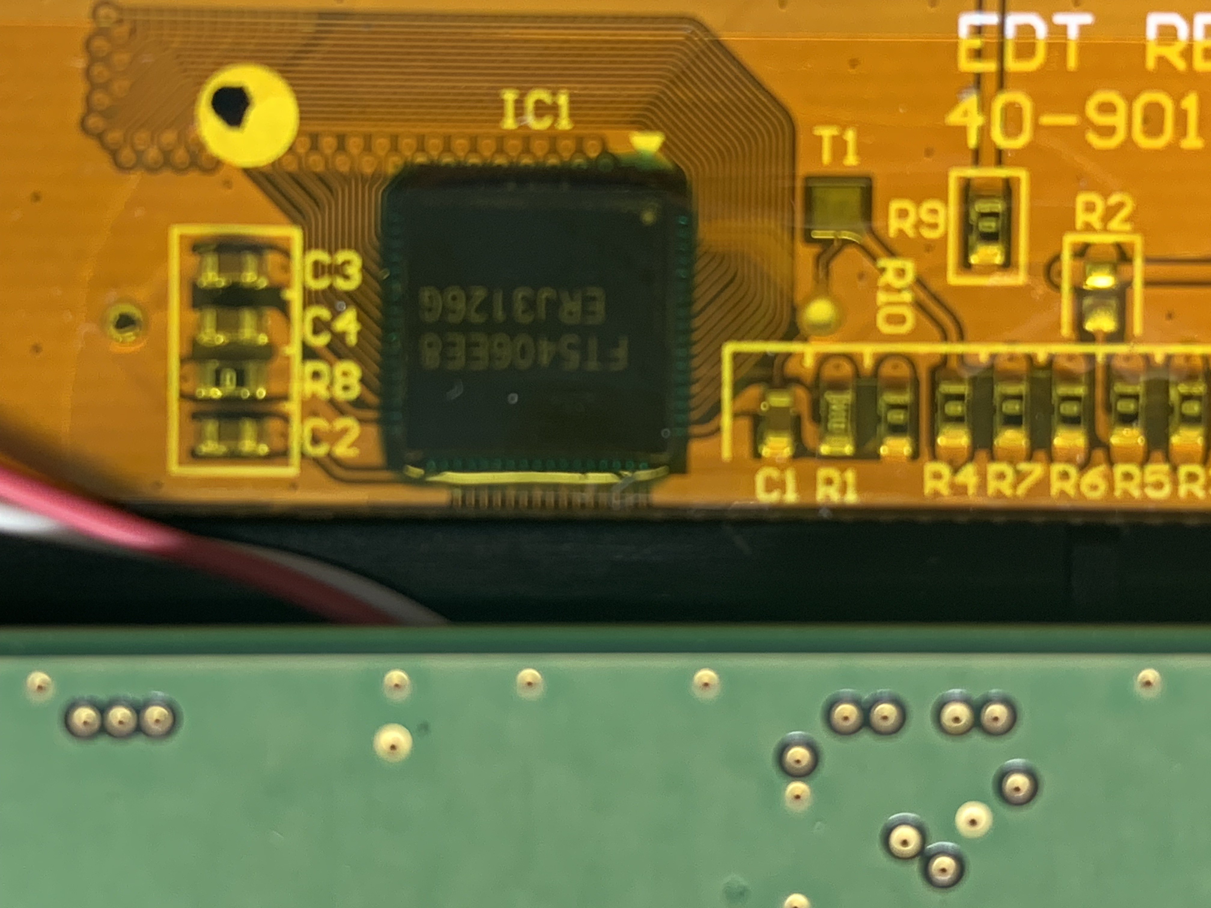
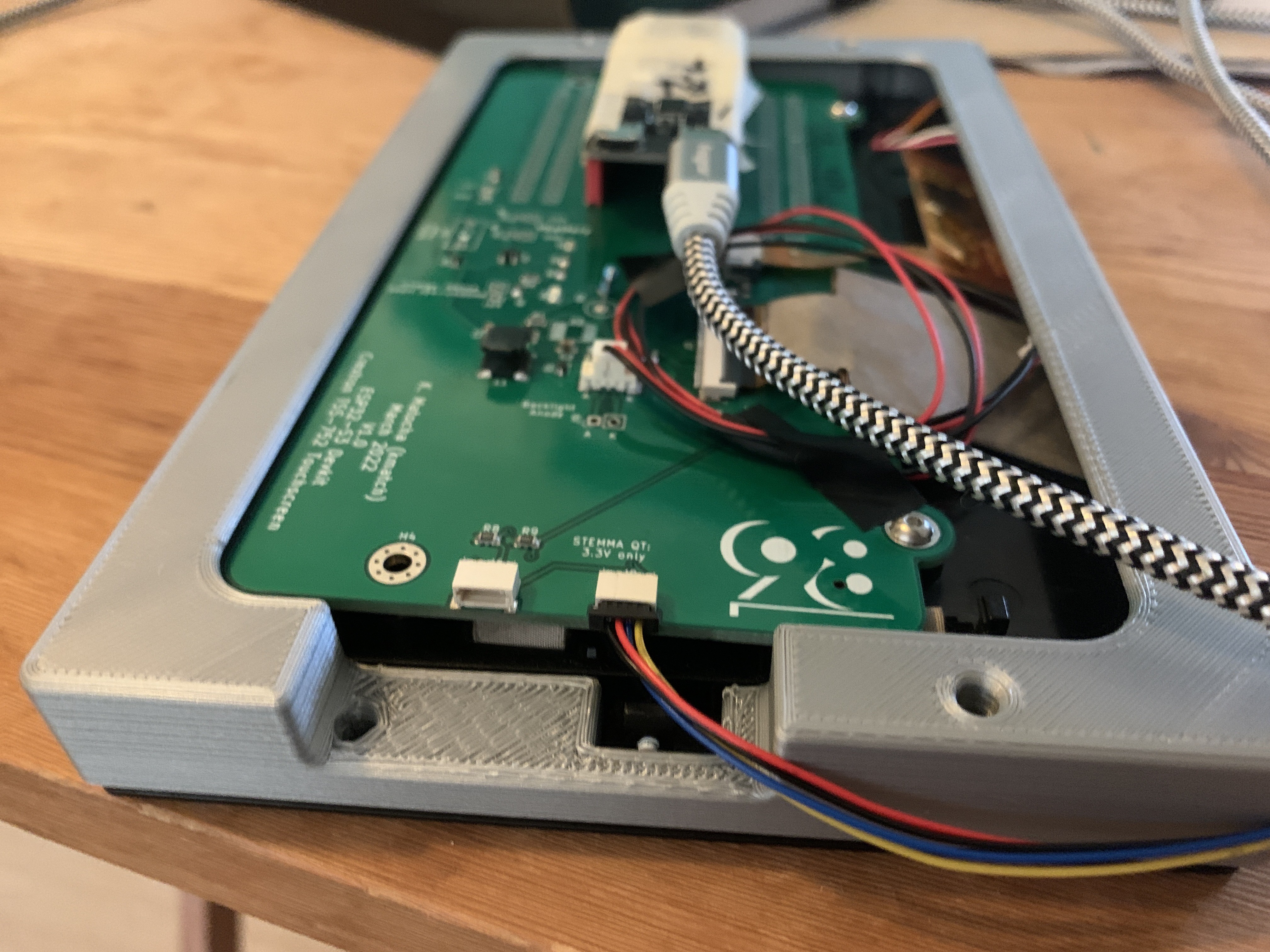
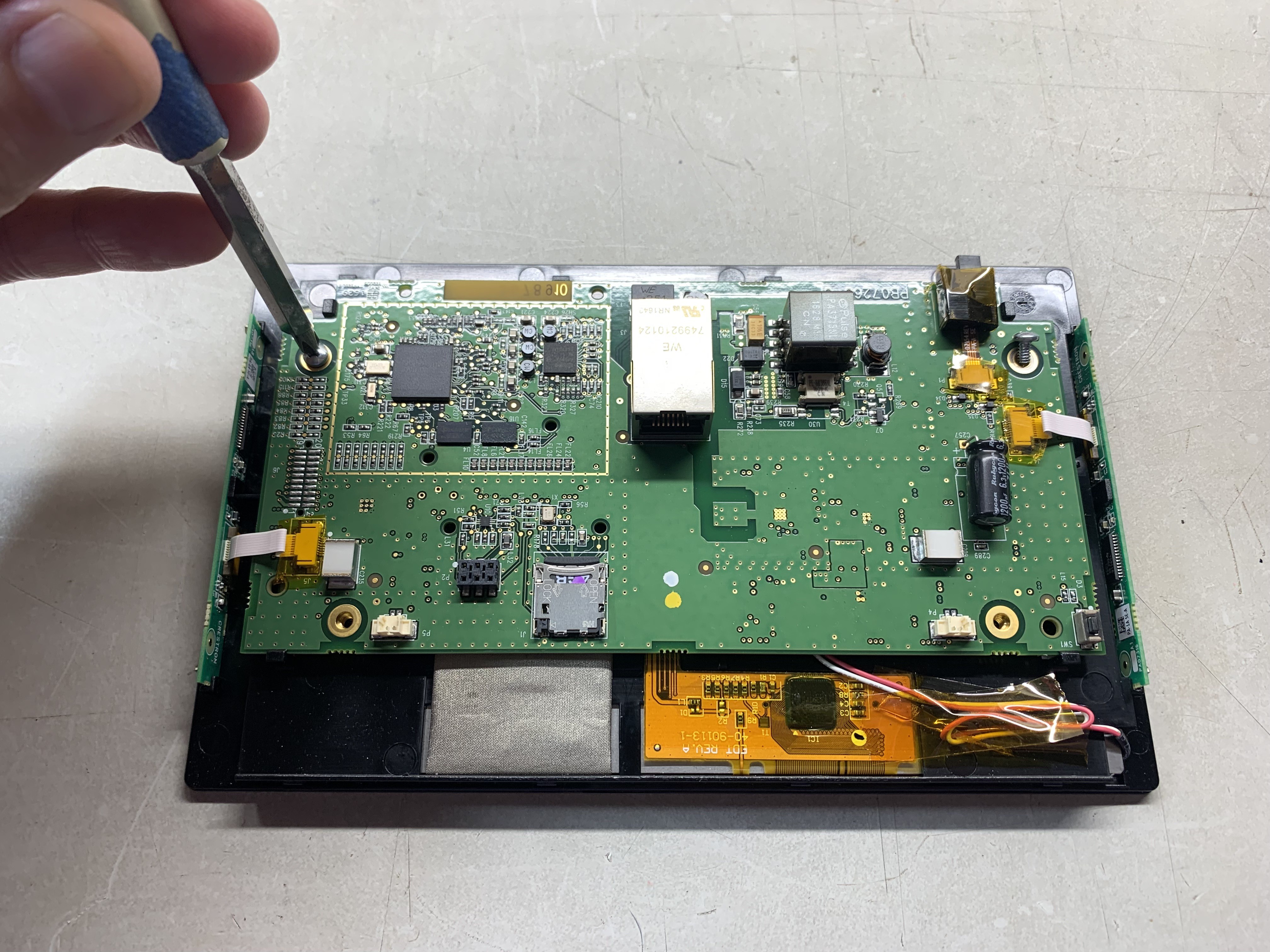
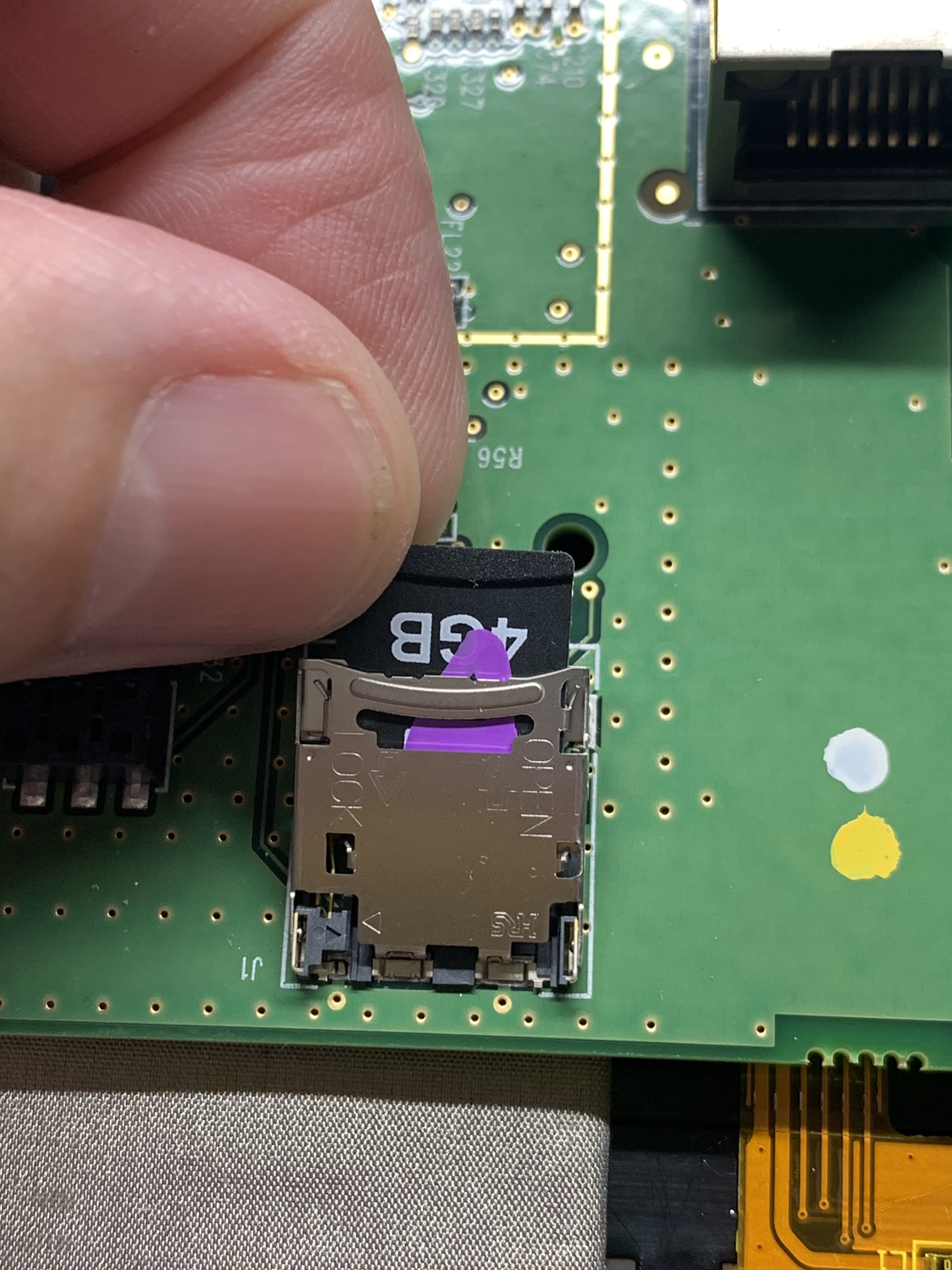
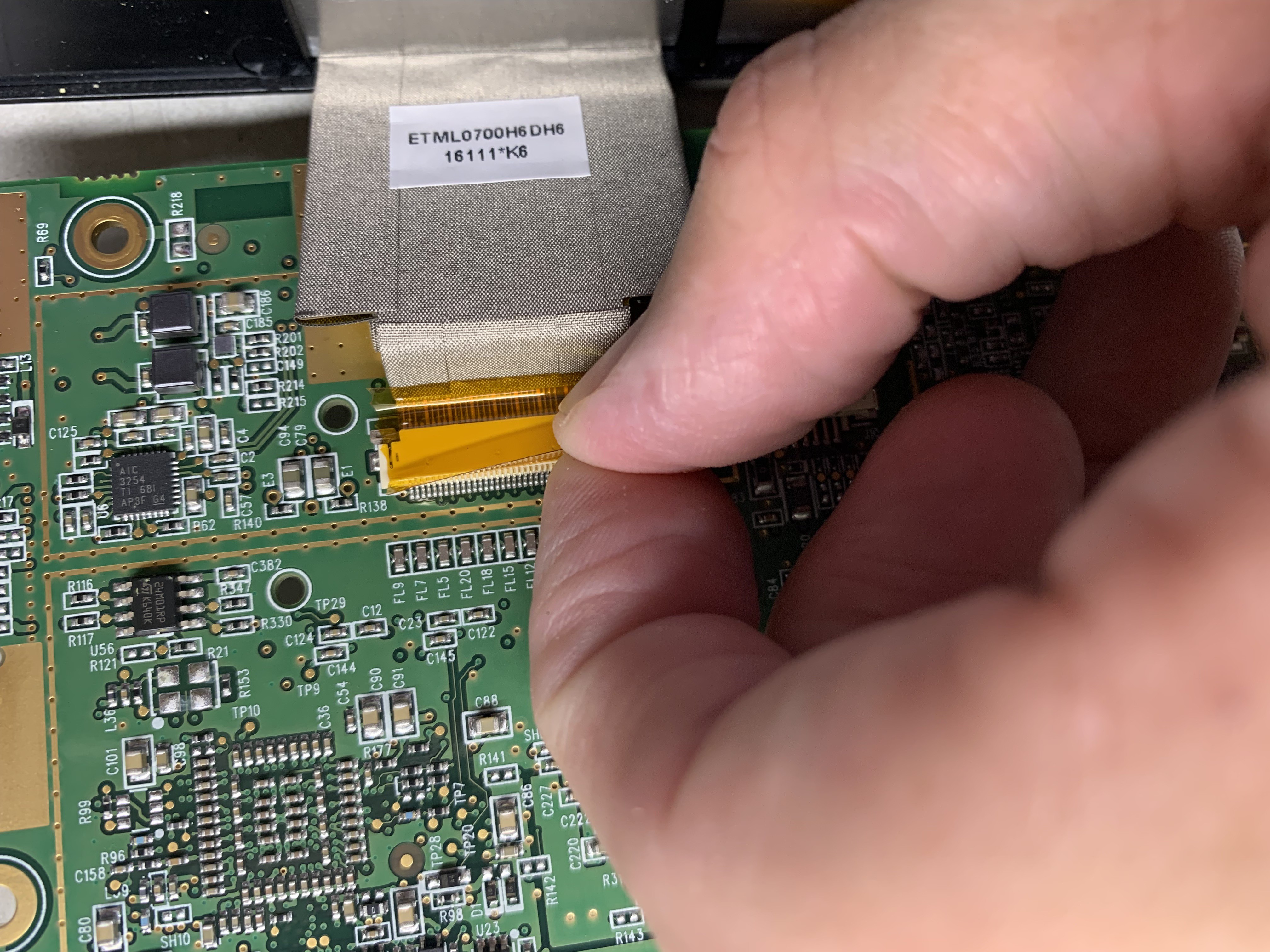
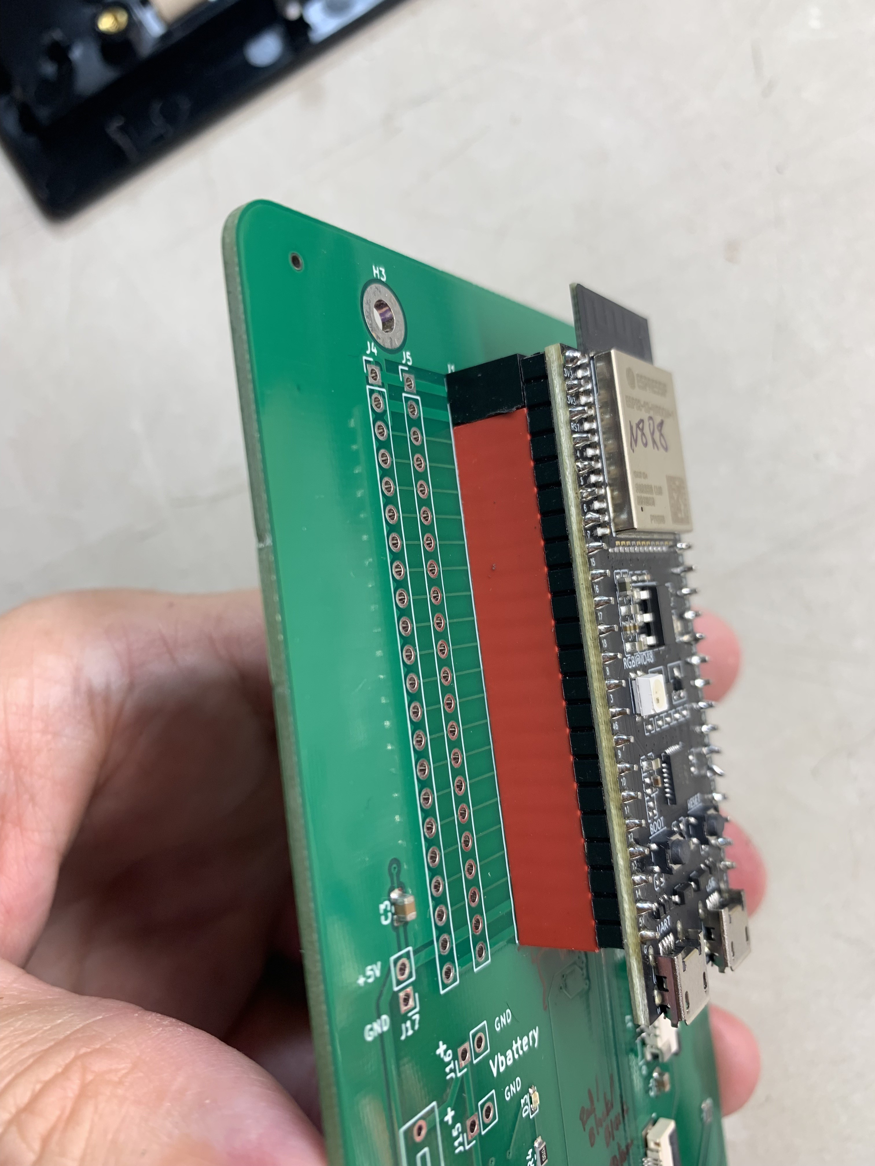
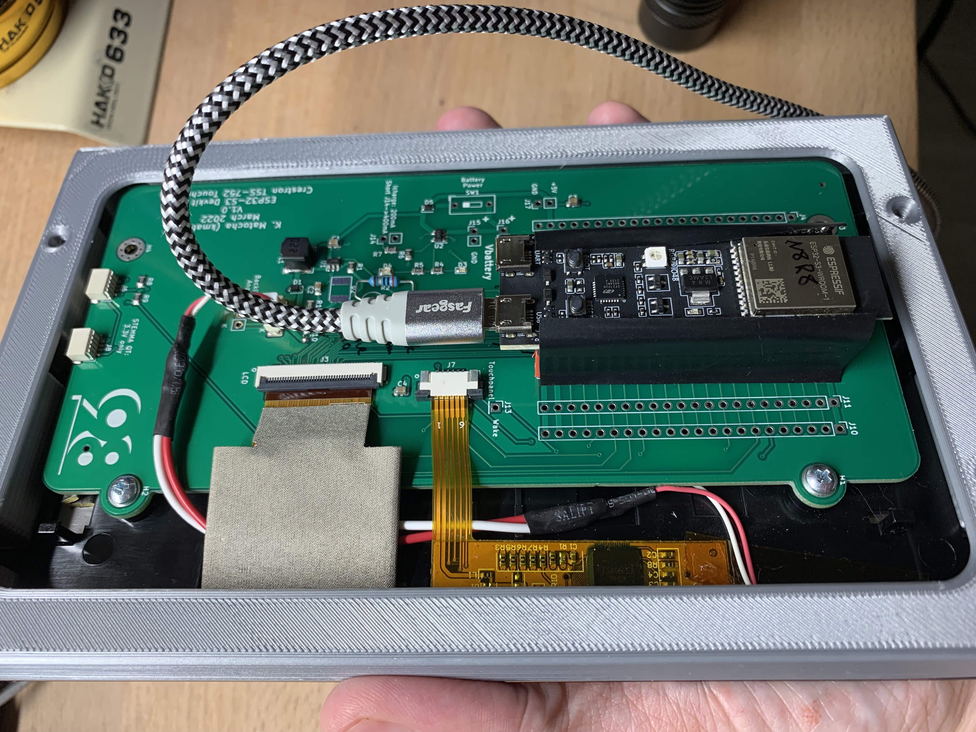
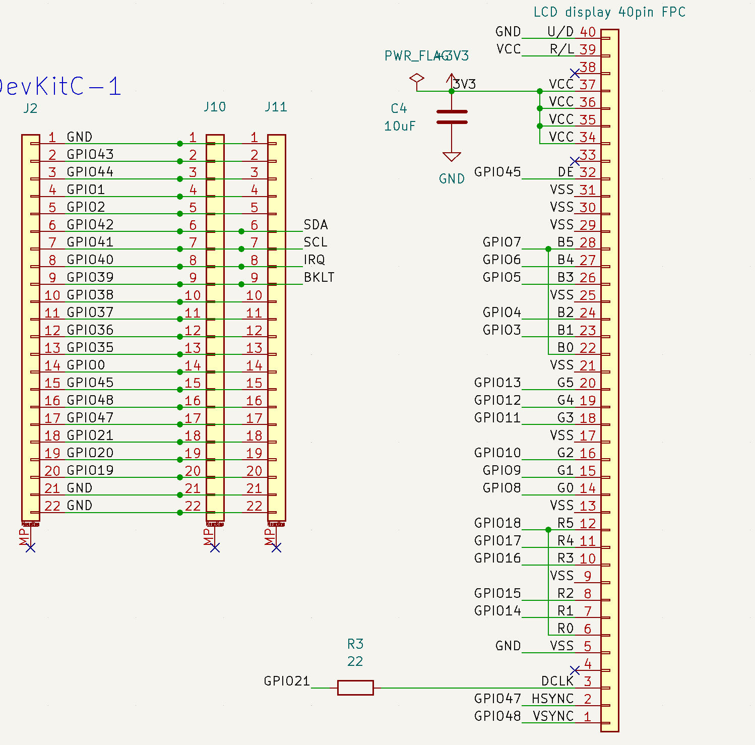
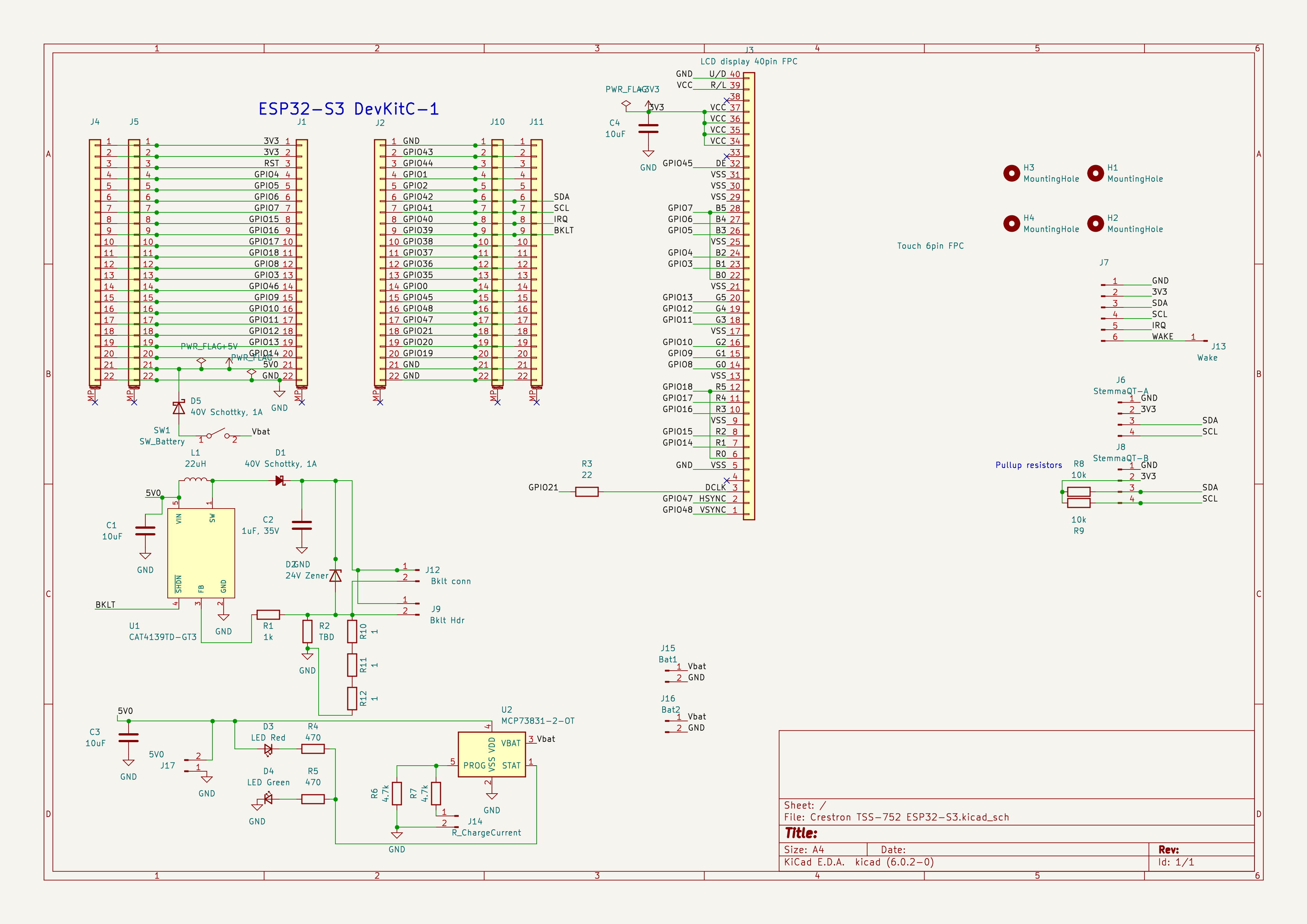
The TSS-752 uses a 40-pin FPC and a quick glance at the connector suggests the pinouts may match the other units display. This is confirmed, the 40 pin FPC and 6- pi. Touch panel pinouts match the TSW-732 I’ve repeated them here for completeness.
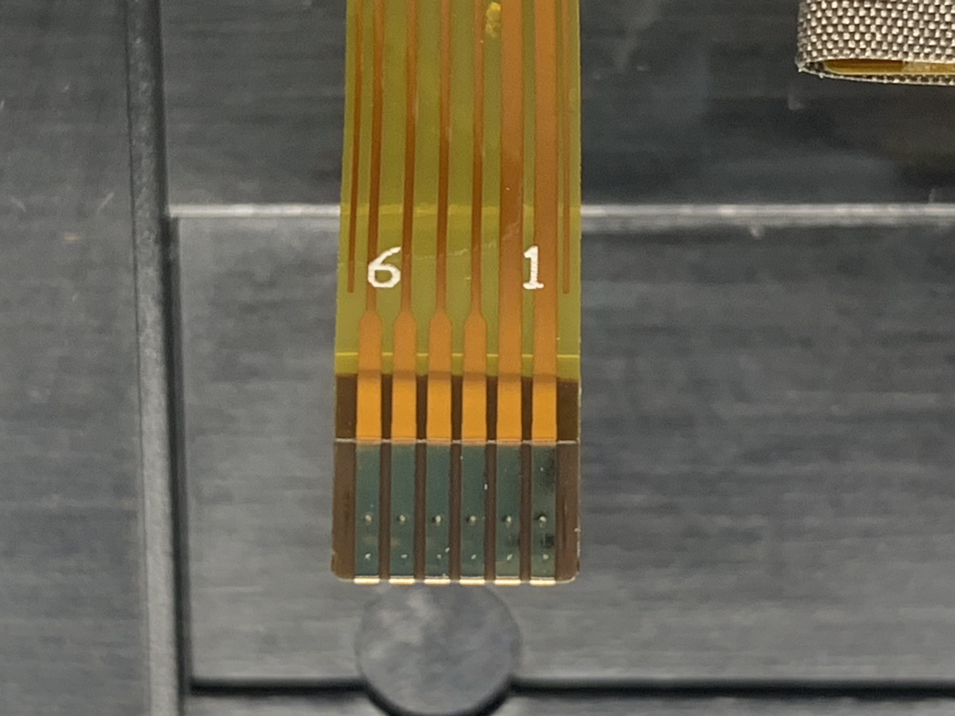
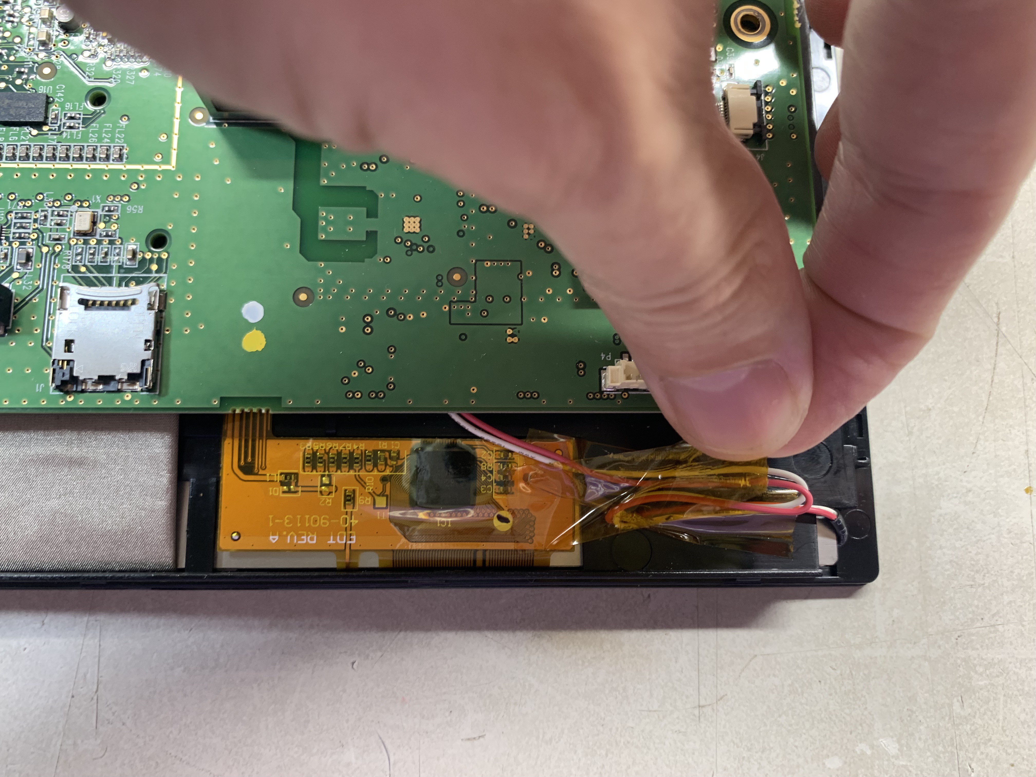
The touch panel driver chip is the same FT5406 and uses a 6-pin FPC. Pinouts are 1: Gnd, 2: 3.3V, 3: SDA, 4: SCL, 5: interrupt and 6: maybe wake but I have not verified. The display is recognized as I2C address 0x38, and a CircuitPython demo using the FocalTouch library. The extra area in the bezel is also touch reactive to access the arrow and X buttons that are labeled on the one edge.
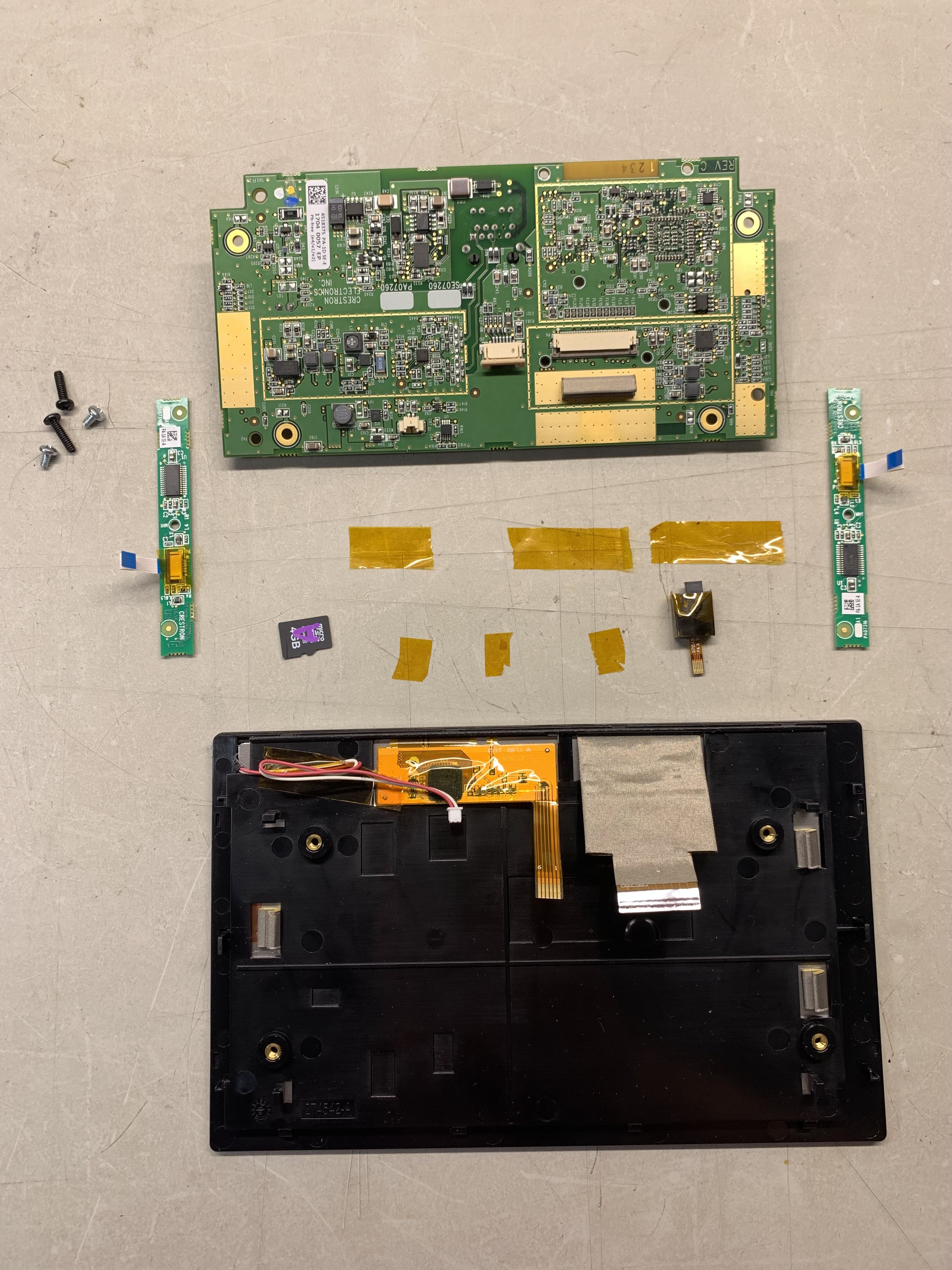
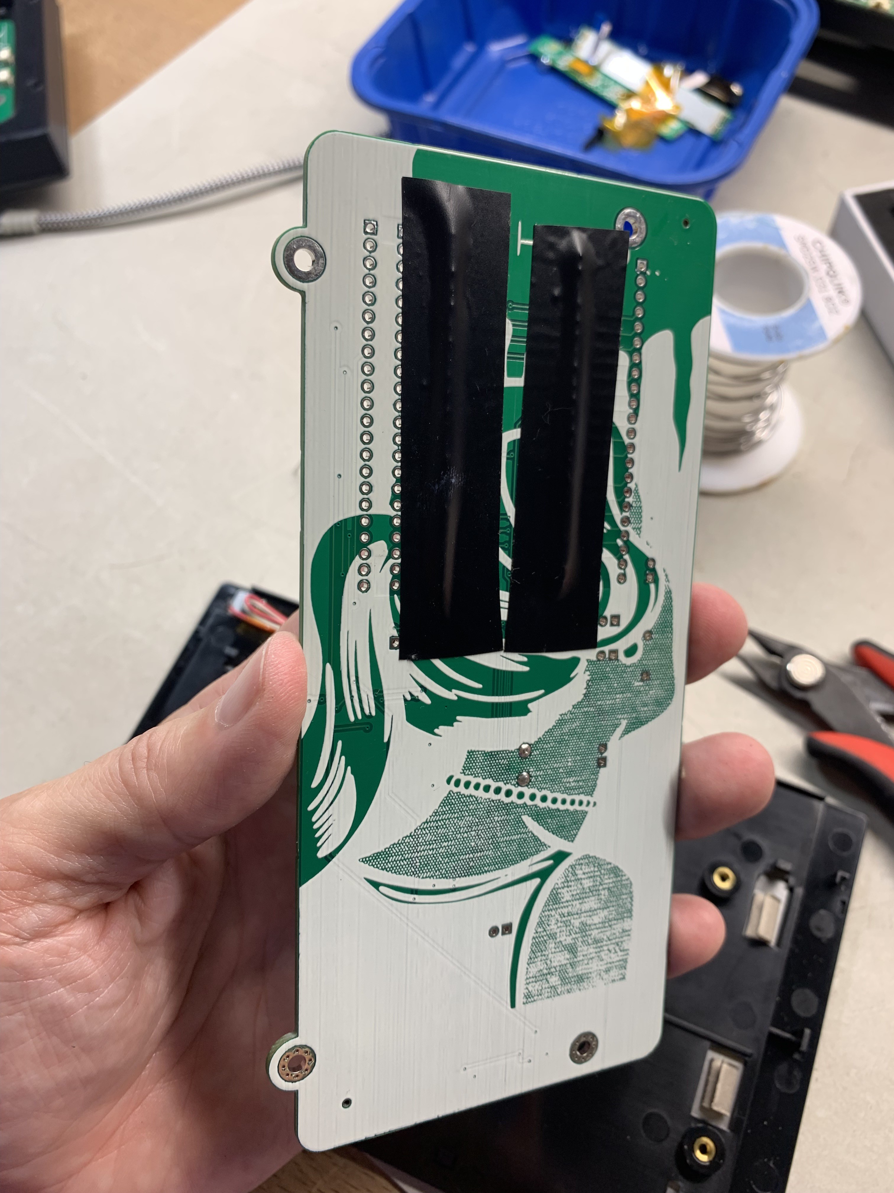
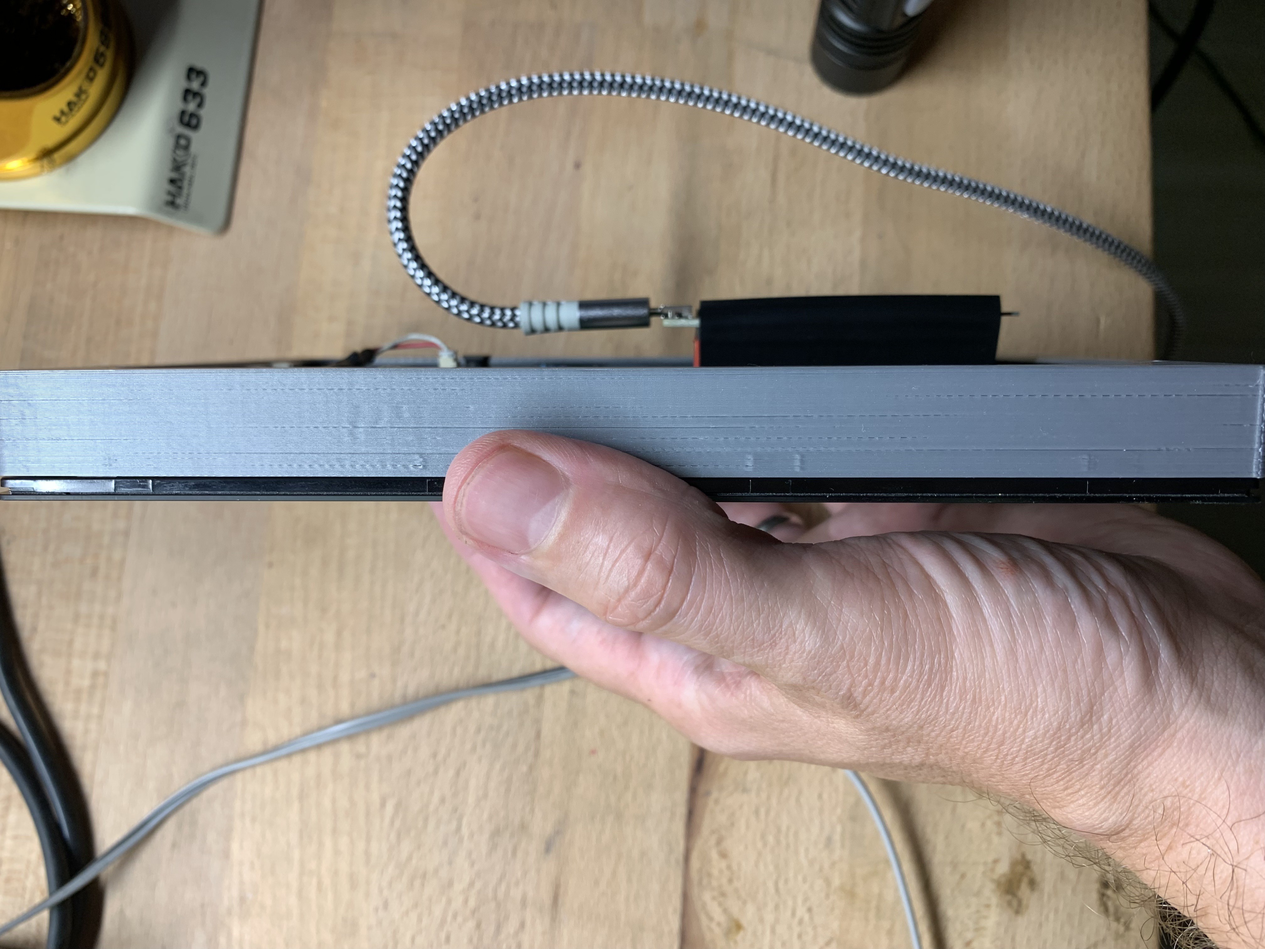
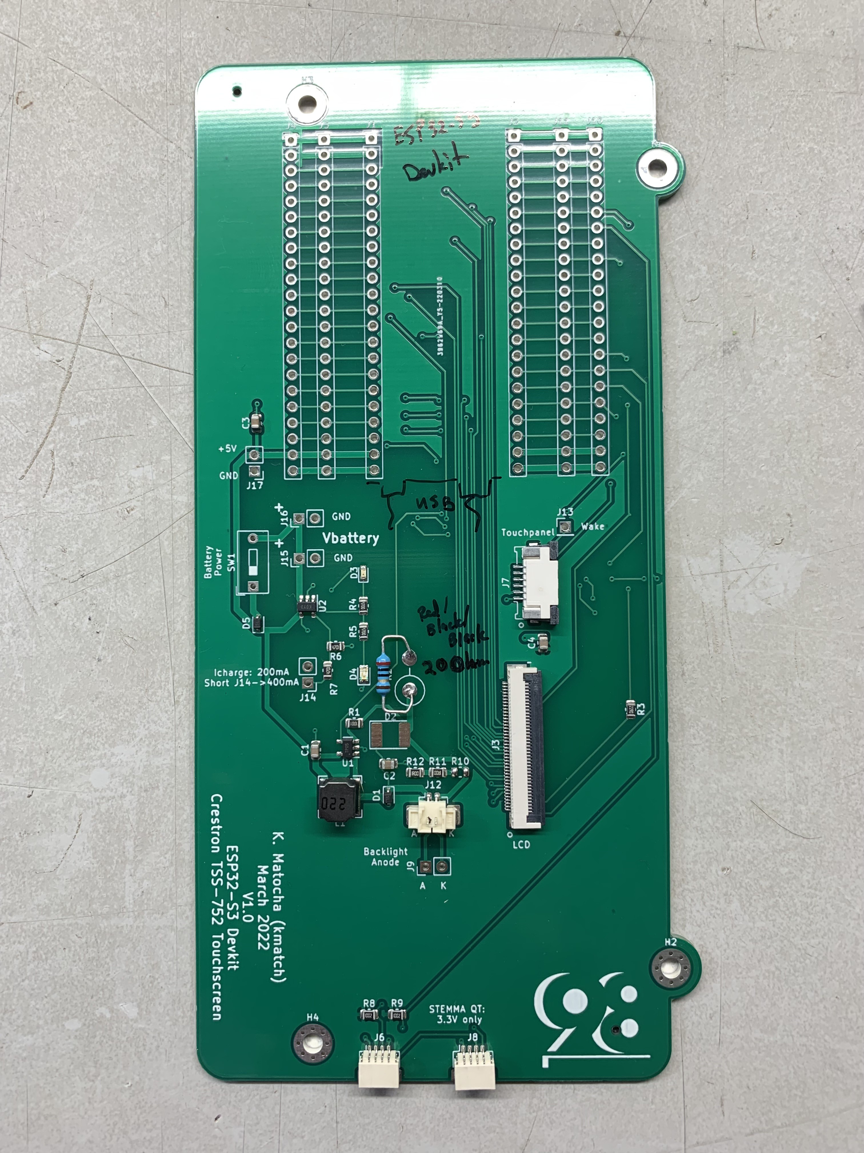
I think this black unit is a winner, the four inset nuts on the back panel are waiting and ready for bolting on a 3d printed or laser cut protective case.
Interestingly both of these units are 303 grams. The black one (model TSS-752) definitely feels dense in the hand. I suspect the diffuser is a heavy hitter in the weight category but I’ll need to separate and weigh the parts to find out. With a battery and a circuit board, this one will be fairly beefy. But nothing really I can do about it, such is life. This process gives me a small appreciation for tablet and phone makers who shave bits everywhere to make such portable devices.
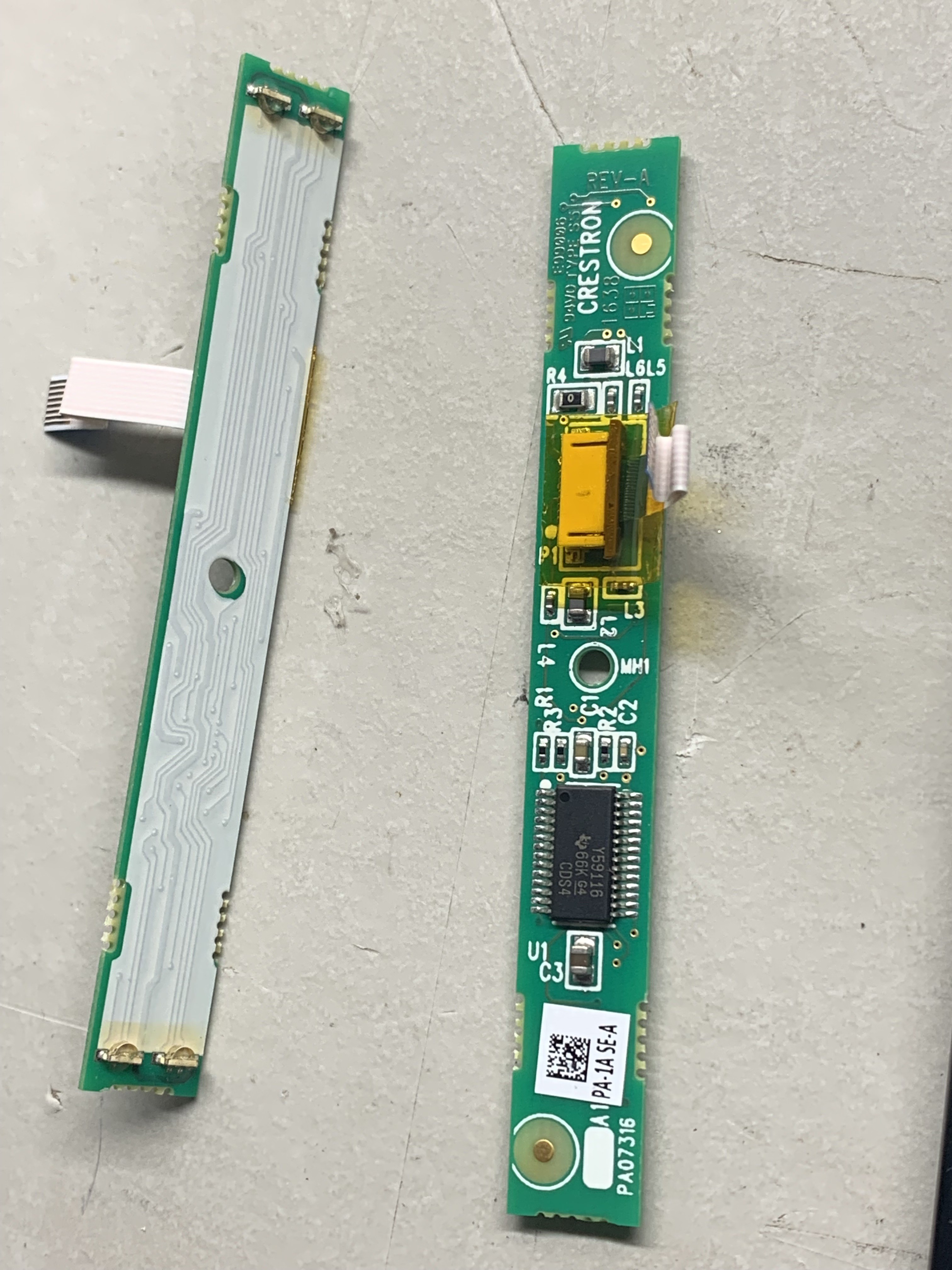
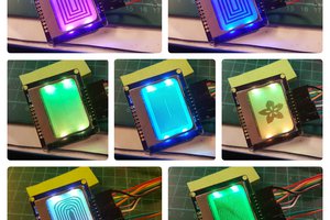
The left and right sides of the unit have red/green occupancy LEDs. This is an interesting way of diffusing the light. I wonder what this coating is on the PCB. Perhaps it is just a reflector. And what is this big chip on here seems way overkill for just an LED driver? Looks like a TI Y59116, and I2C constant current LED driver. Maybe these could be repurposed for something cool.

 davedarko
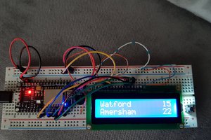
 terryspitz
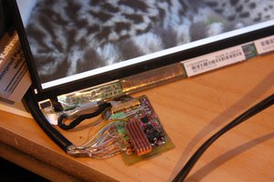
 Jared Sanson
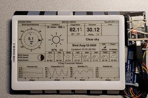
Who did you use for the assembled HACKtablet PCB prototype? I want to order a couple and im just getting my feet wet with this kind of thing