 kmatch98
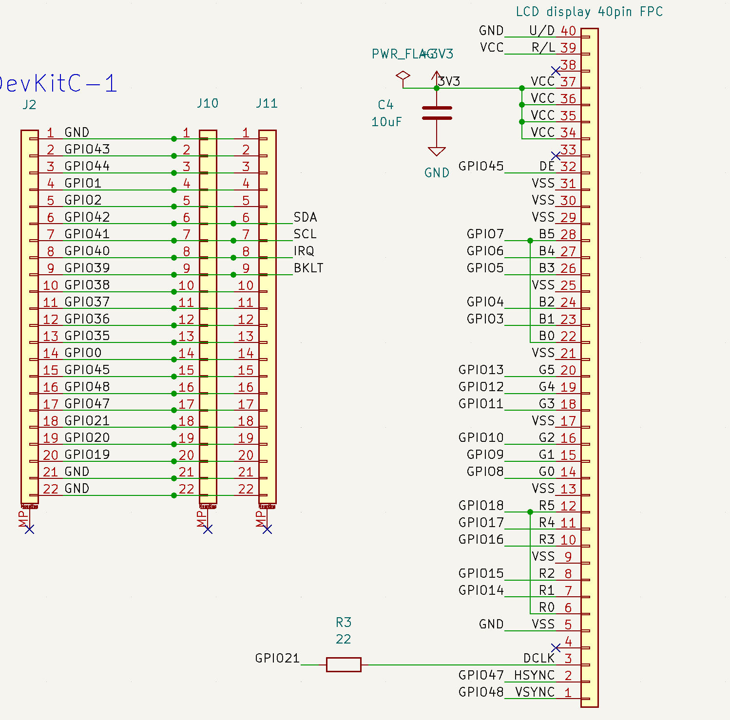
Here is a summary of the pinouts between the ESP32-S3 devkit board and the I2C bus (including two Stemma QT connectors) and also the 40-pin LCD display taken from the TSS-752.
The I2C signal connections are GPIO41 (SCL) and GPIO42 (SDA). The touchscreen IRQ is connected to pin GPIO40.
The backlight enable is connected to GPIO39.
Here is the schematic for the Prototype PCB that I created for the connections between the TSS-752 extracted touch-screen display and the ESP32-S3 devkit board.
This is my first schematic so it's probably not very readable. I've got a lot to learn.
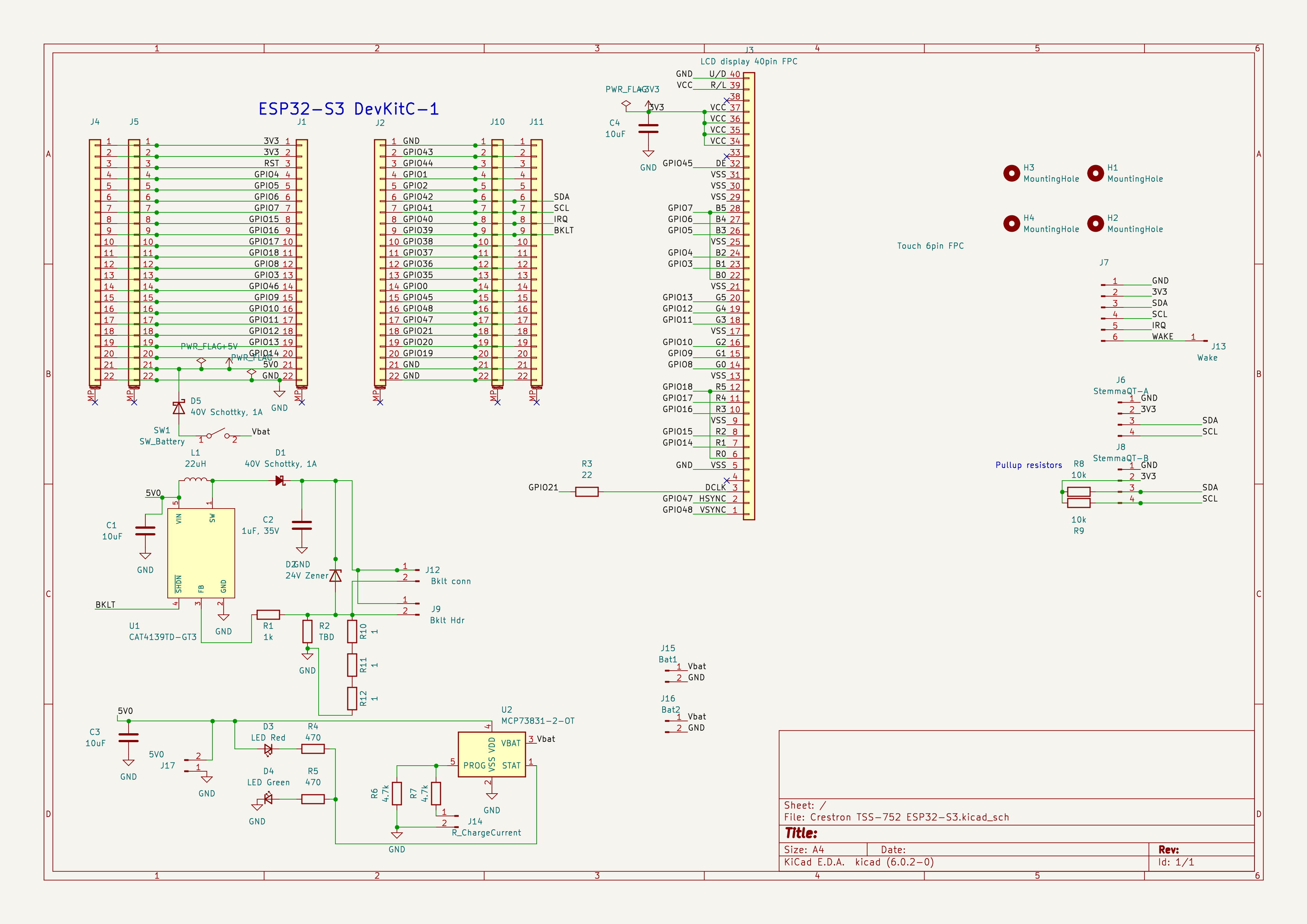
During initial testing, I found that the backlight current was set too high (and I burnt out U1), so I made a modification to the board backlight driver current setting. I removed R10 to open circuit the 3 Ohm resistance, and placed a 20 Ohm resistor in position R2. (Next time I need to provide more copper area to U1 of heat sinking.)
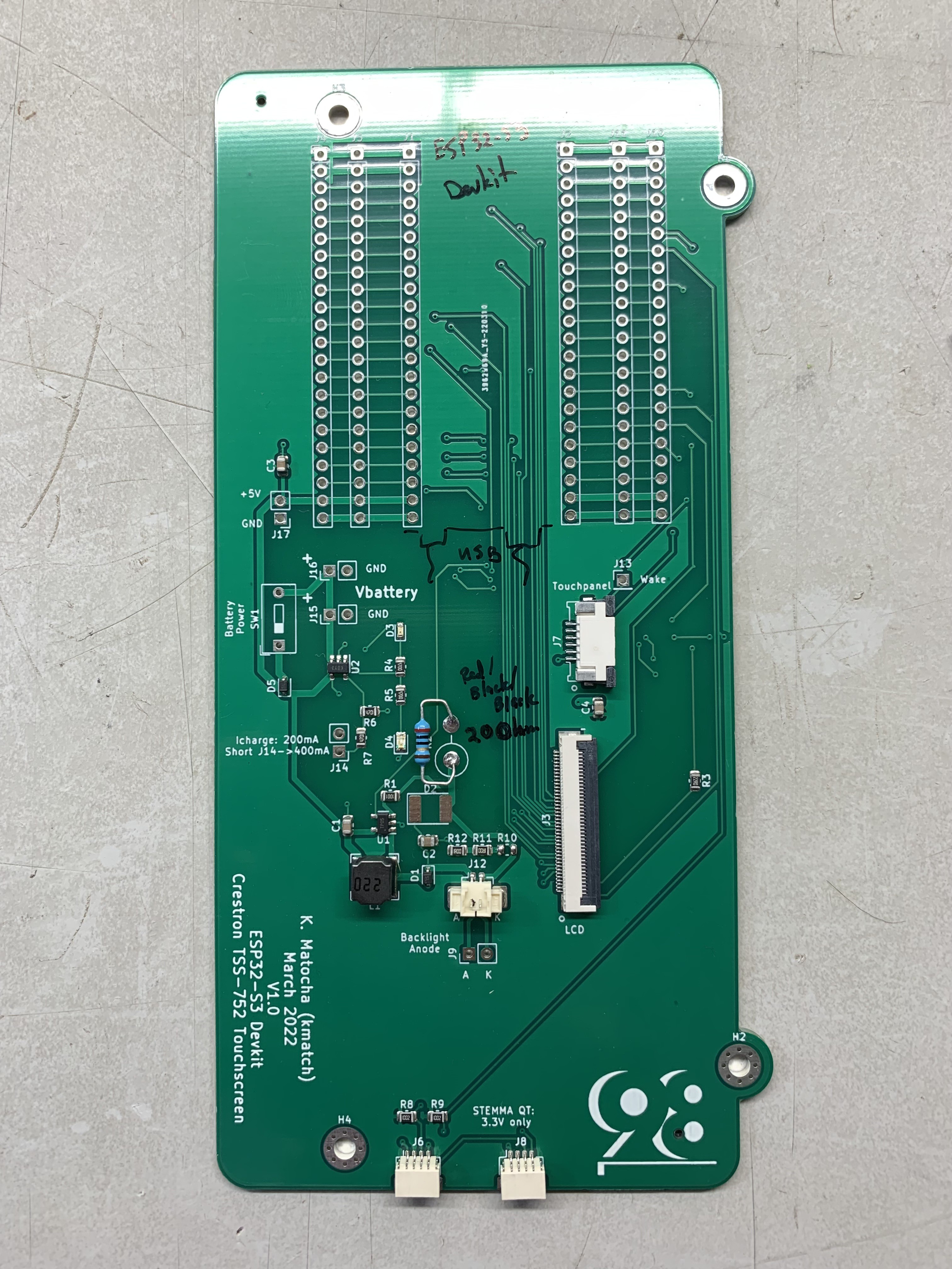
Also, I had to extend the wires to the backlight so that the connector would reach.
Here's an image of the board with R10 removed, and the 20 Ohm resistor placed in position R2. Also note the orientation of the devkit board, with the USB ports noted.
Discussions
Become a Hackaday.io Member
Create an account to leave a comment. Already have an account? Log In.