 kmatch98
Here are the steps for detaching the screen from the TSS-752, and then installing the ESP32-S3 demo board.
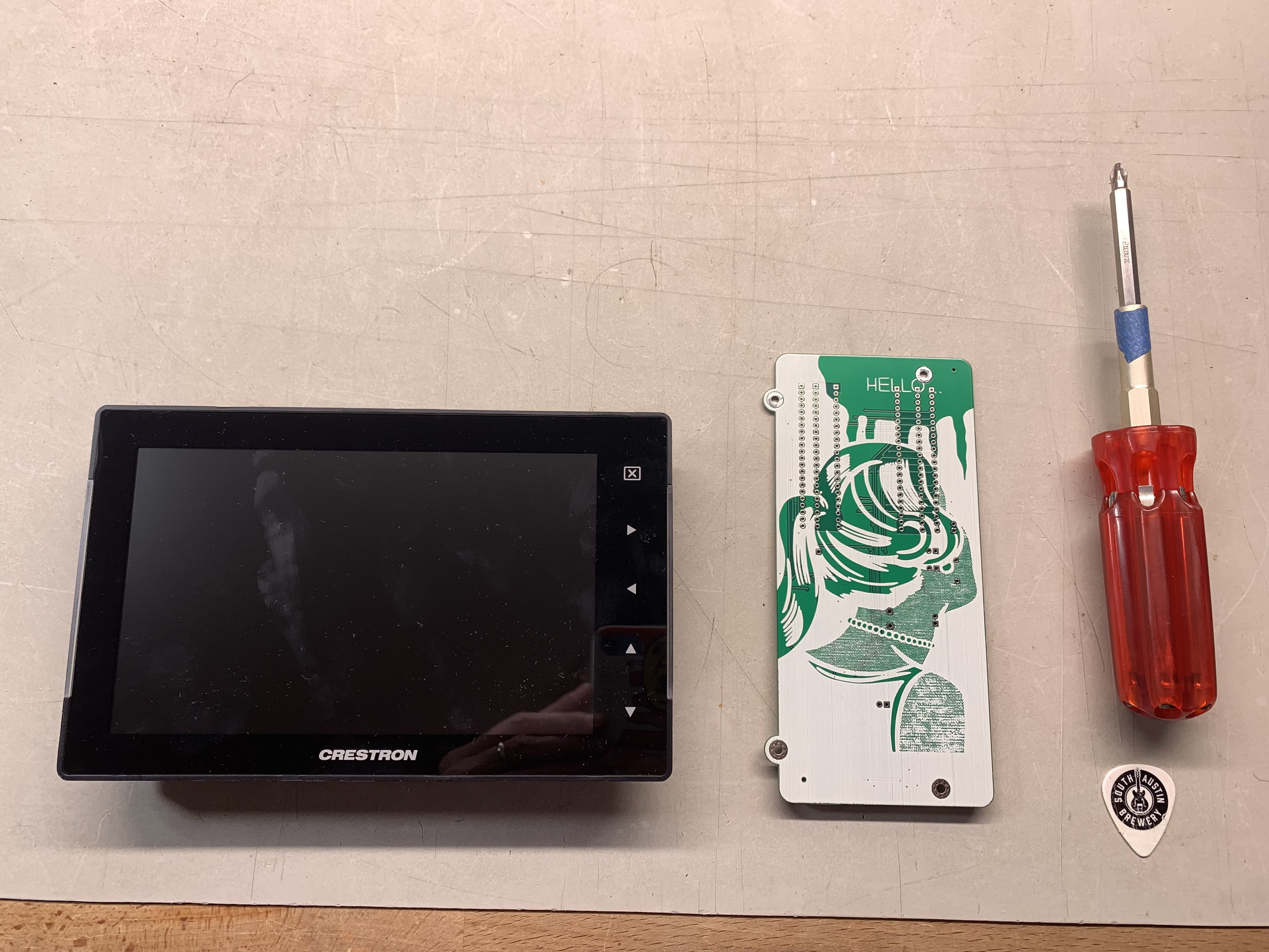
Procure a Crestron TSS-752 and a custom circuit board. You'll need a Philips screwdriver and a spudger (I use a stiff guitar pick).
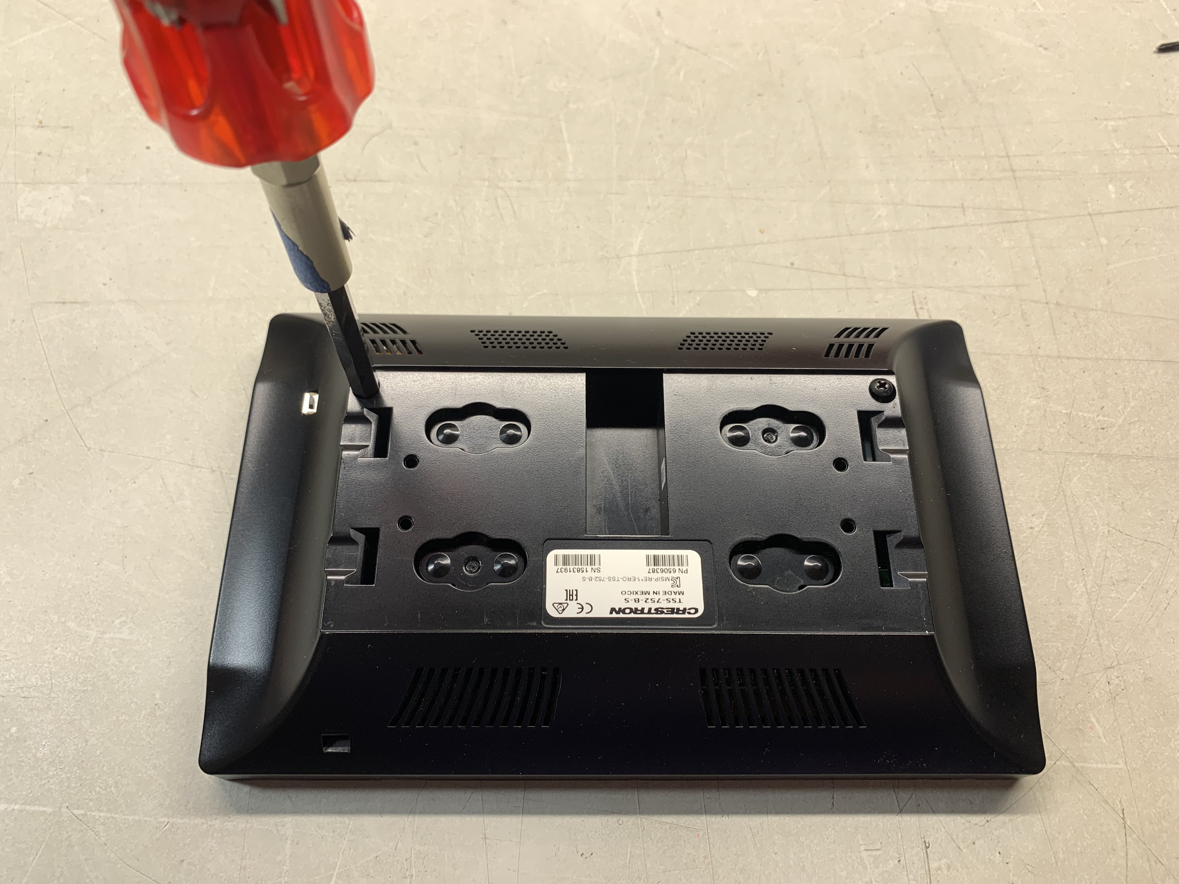
Remove two M2.5 screws with a Philips screwdriver.
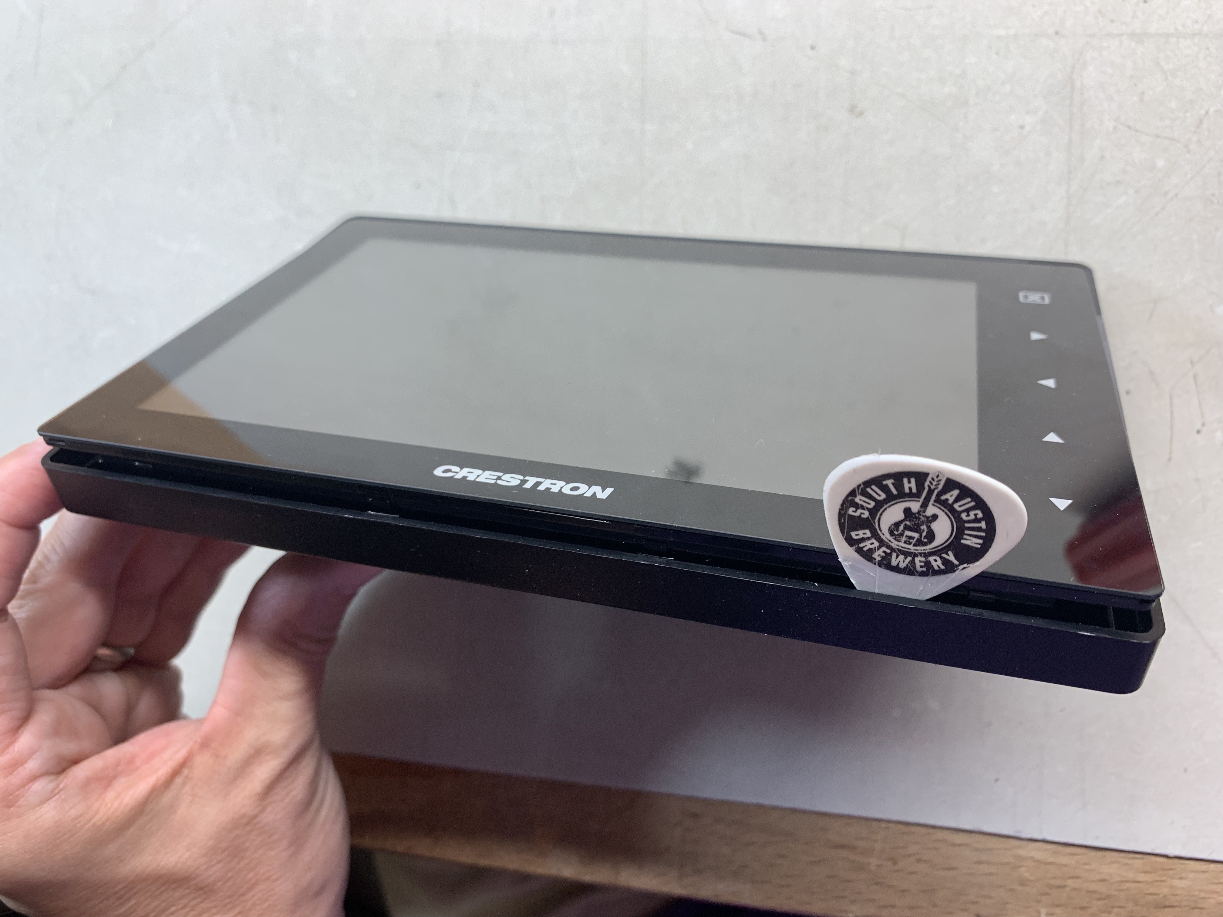
On the edge with the Crestron logo, insert the guitar pick and slide it back and forth to release the clips between the housing and the display bottom edge.
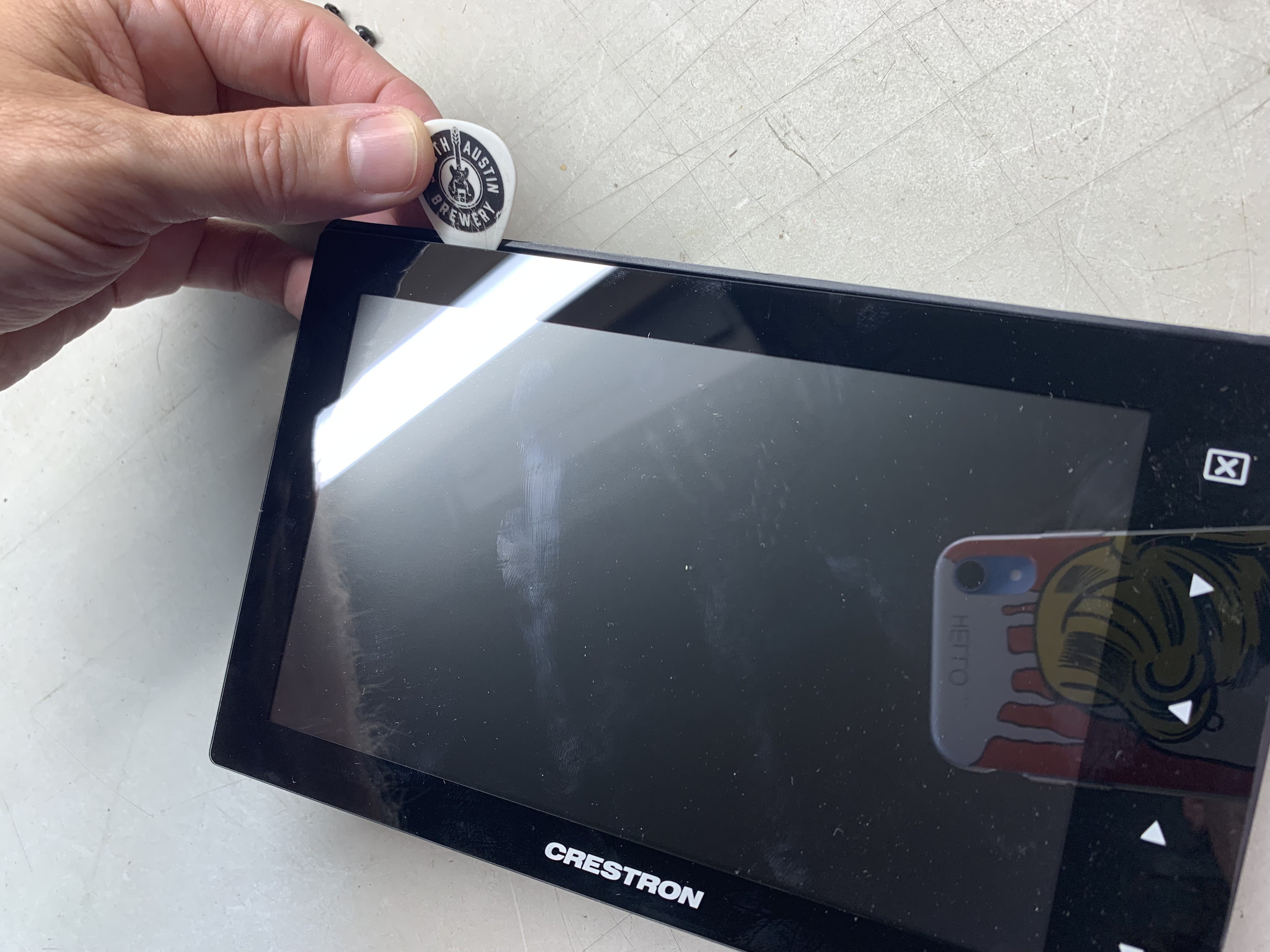
Now, do the same with the upper edge. The order of the edges is important.
Pry off the back cover and remove the two speaker connectors (red and black twisted wires) to disconnect the main panel from the back housing.
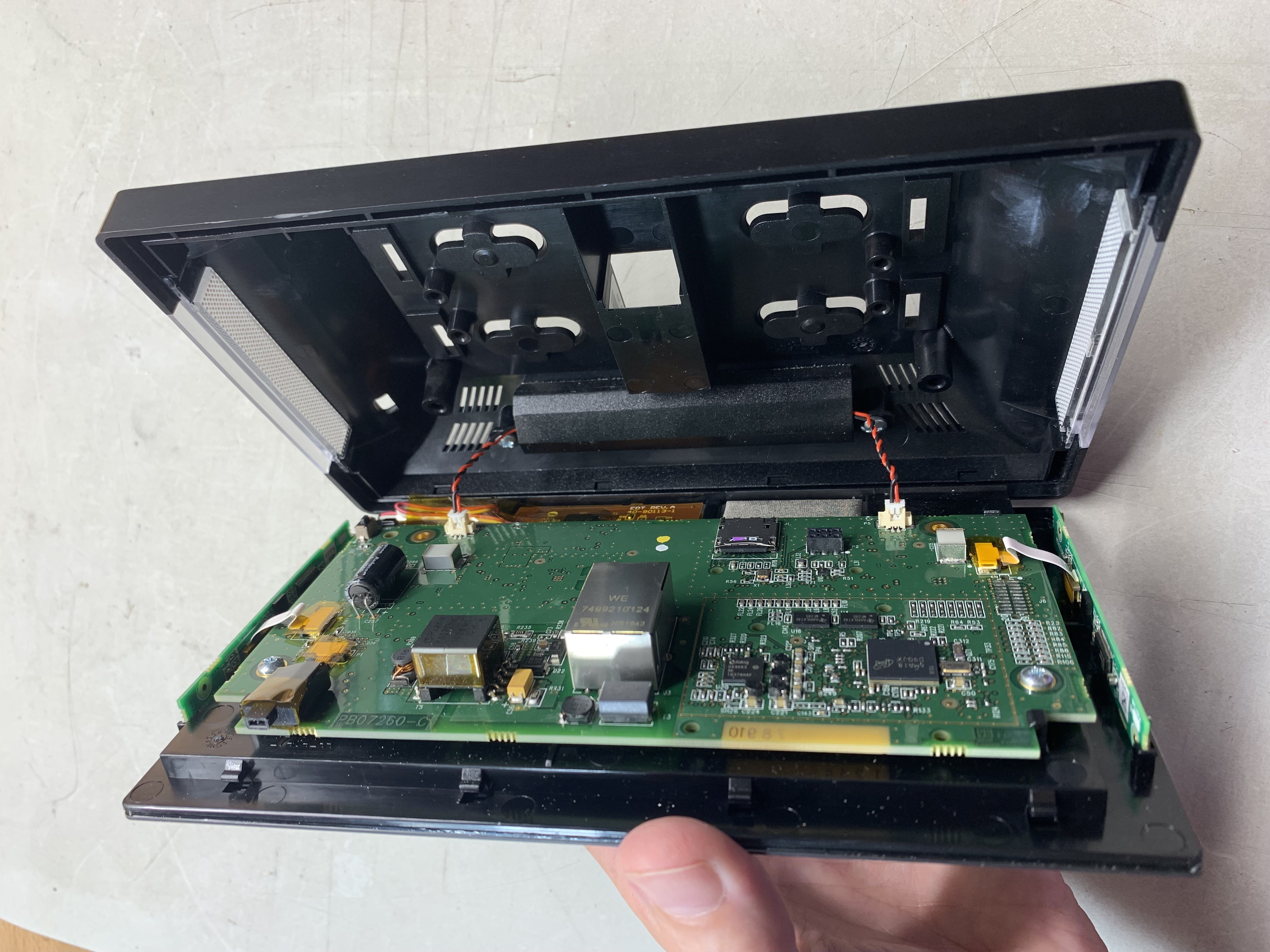
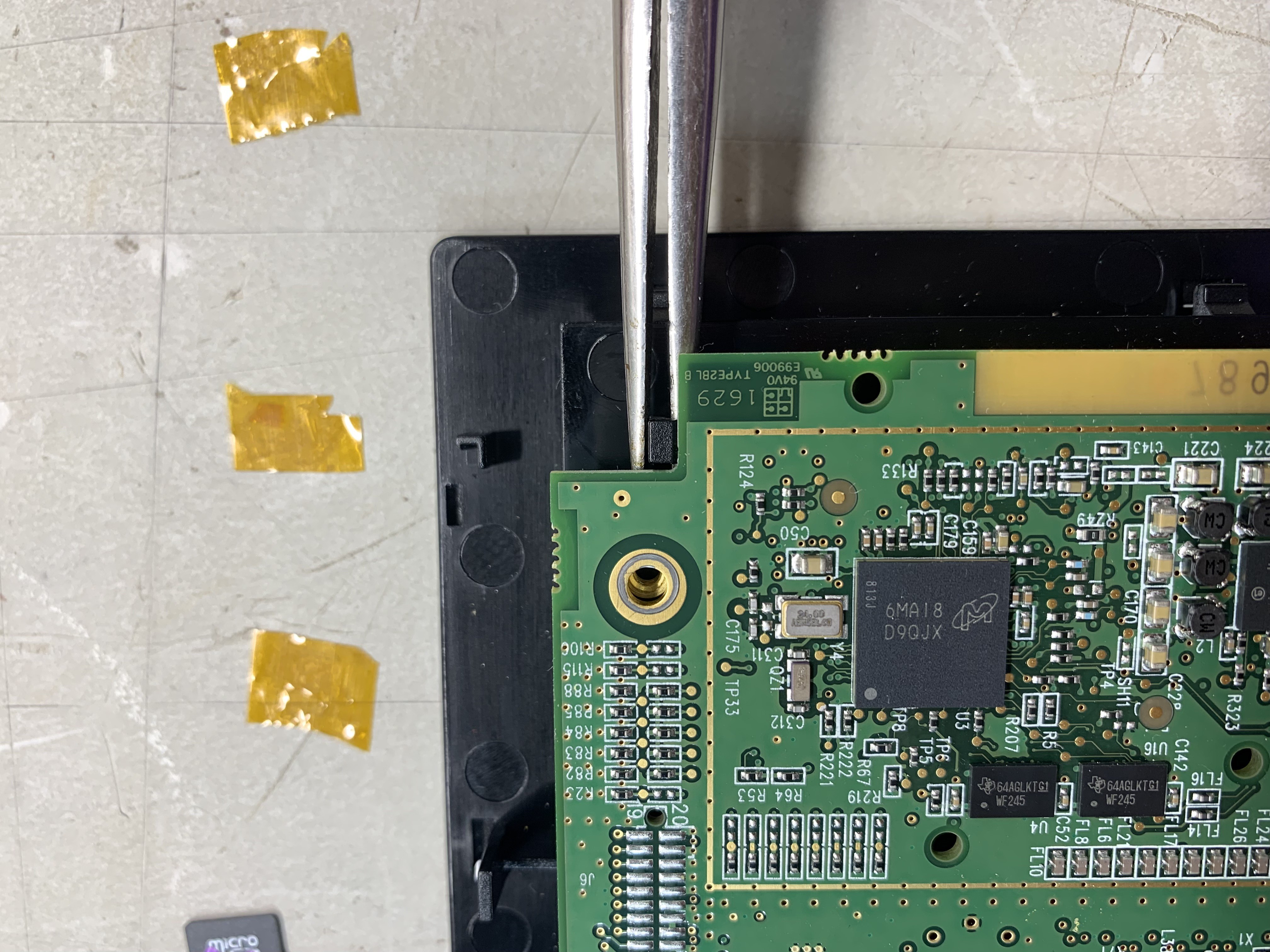
Remove two more Philips screws.
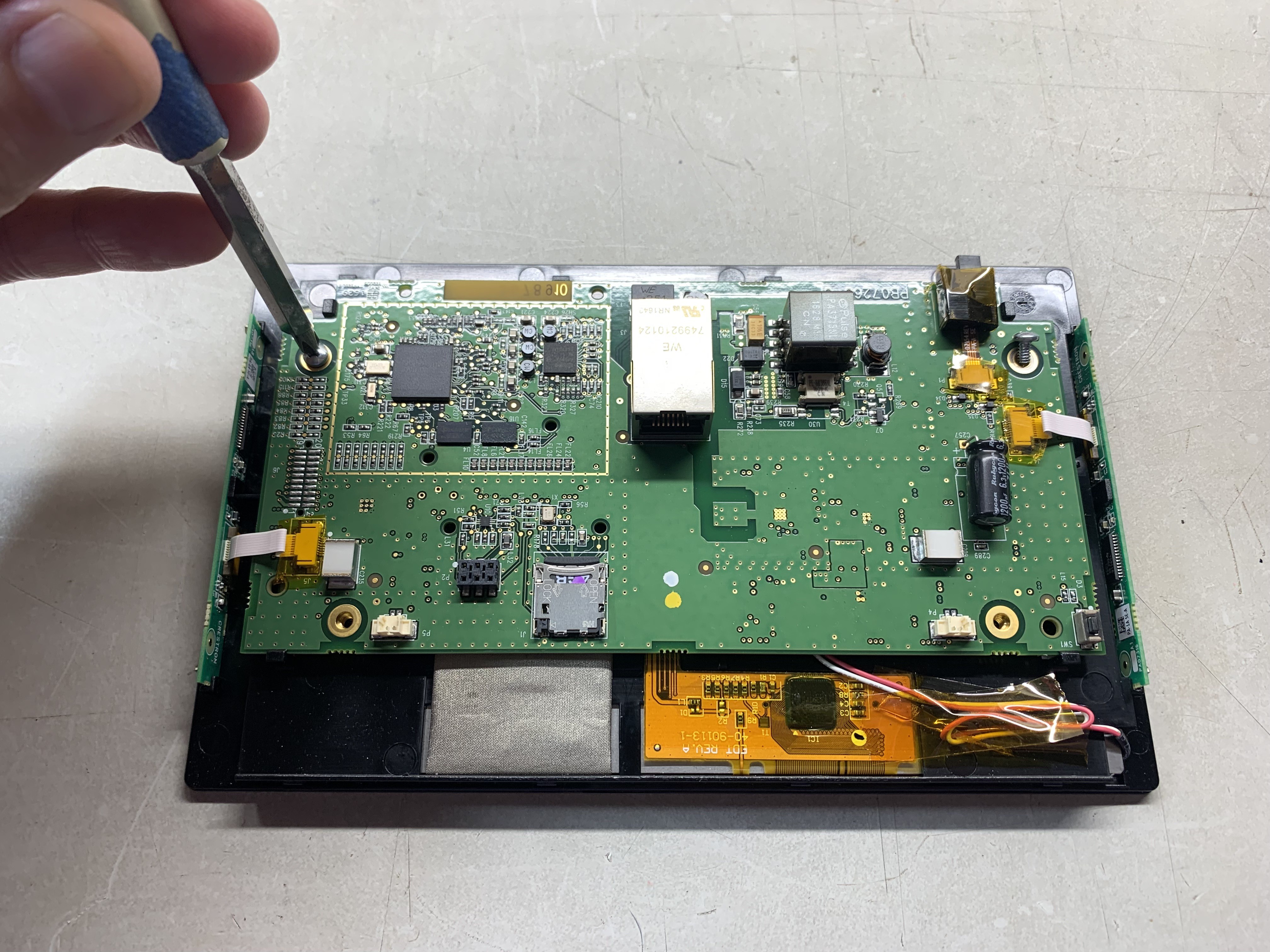
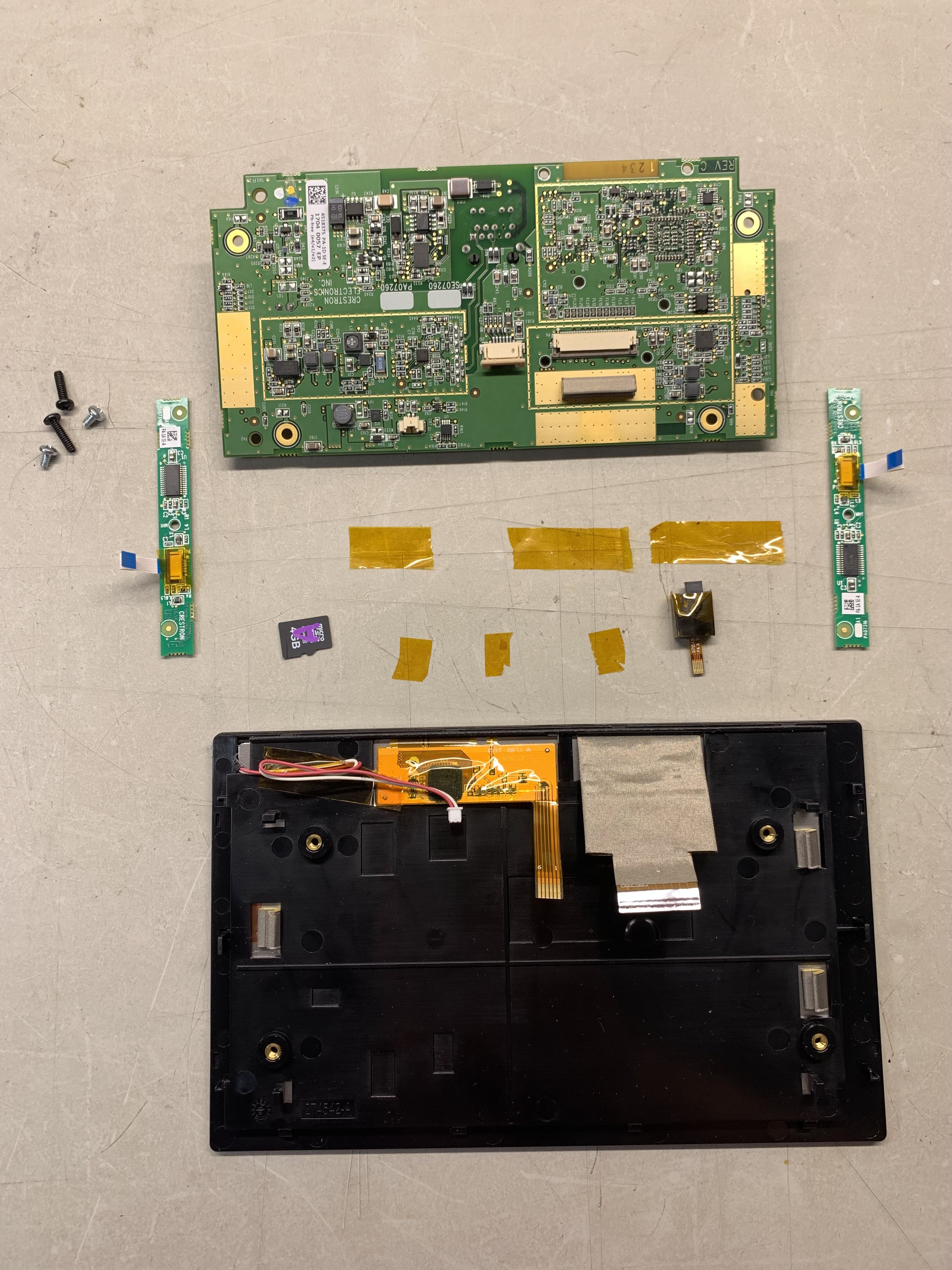
Peel off the brown (Kapton) tape from the connector cables and disconnect the flex cables. The two connectors on the left and right go to the LED and LED driver boards with I2C control. Maybe you can reuse those for another cool project. I'm not sure what the other cable goes to, but remove it anyway.
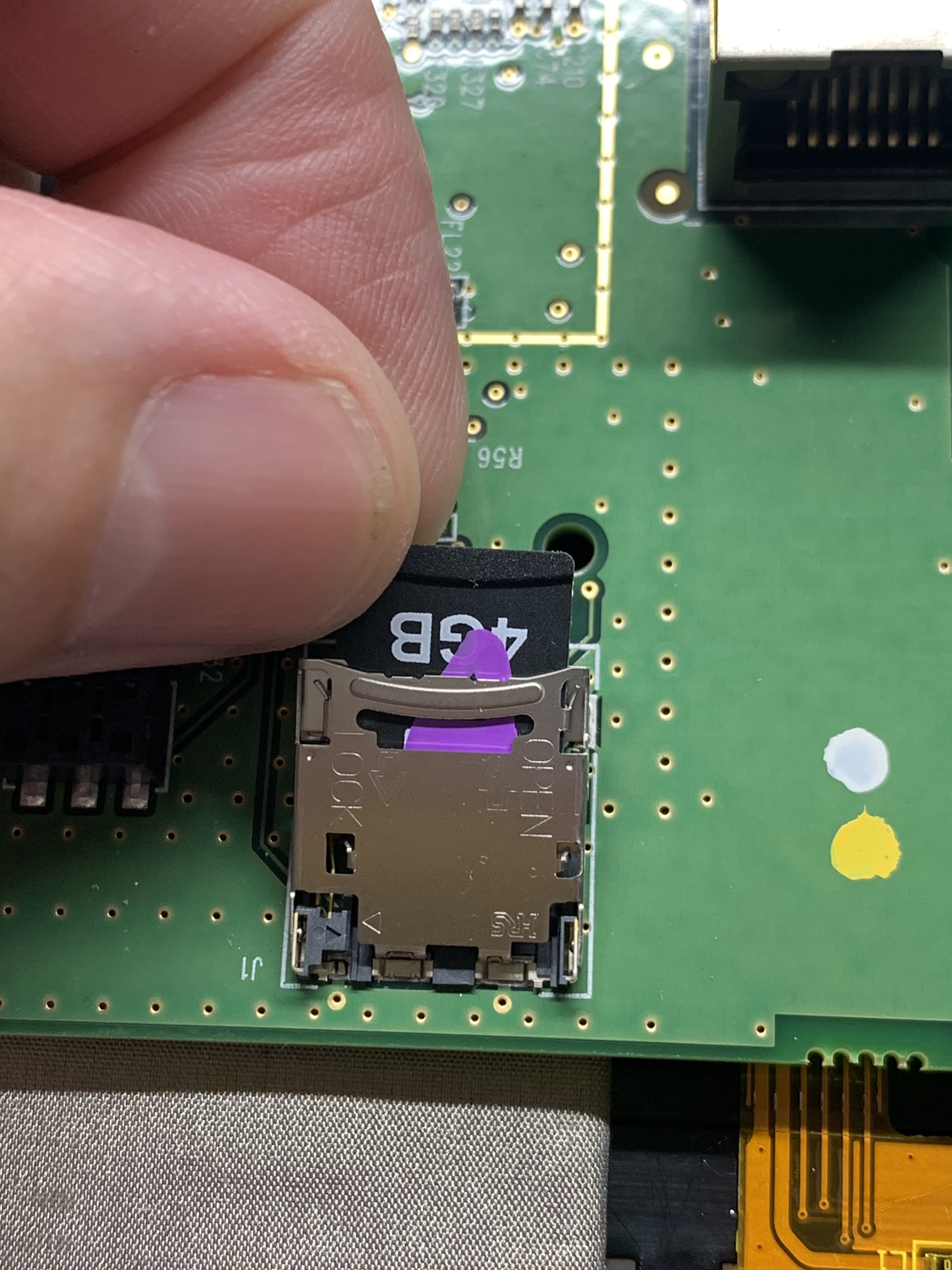
Now, remove the 4Gb memory card. It's in a weird format, but you can reformat it and use it for something else.
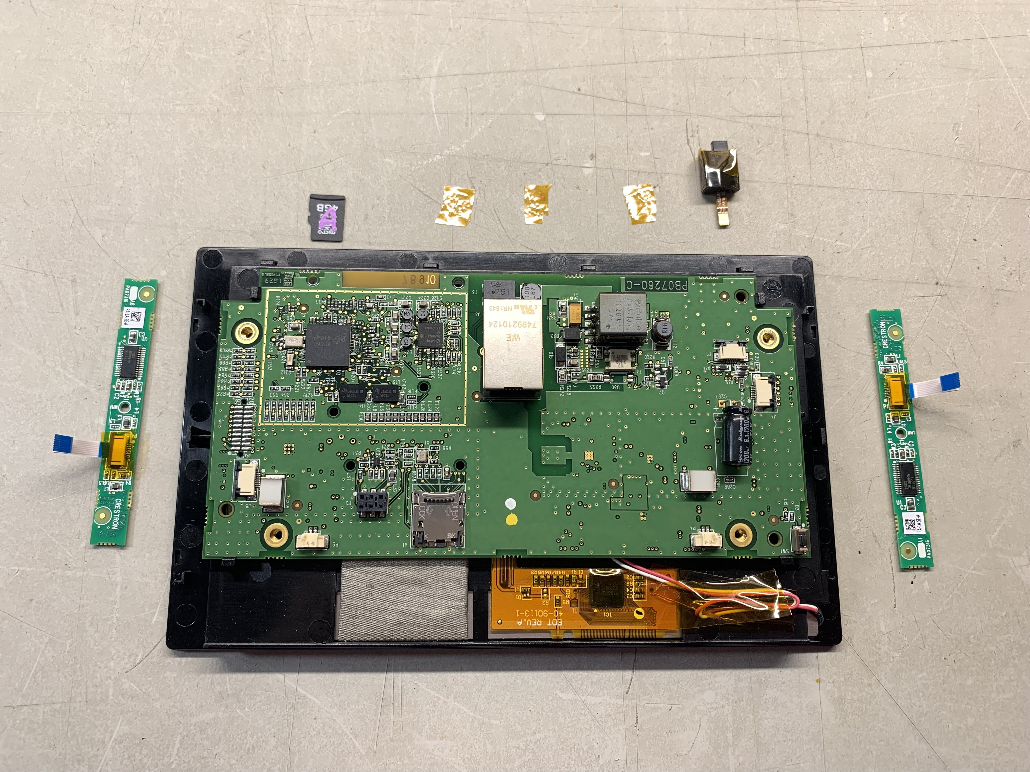
Here's the parts I removed:
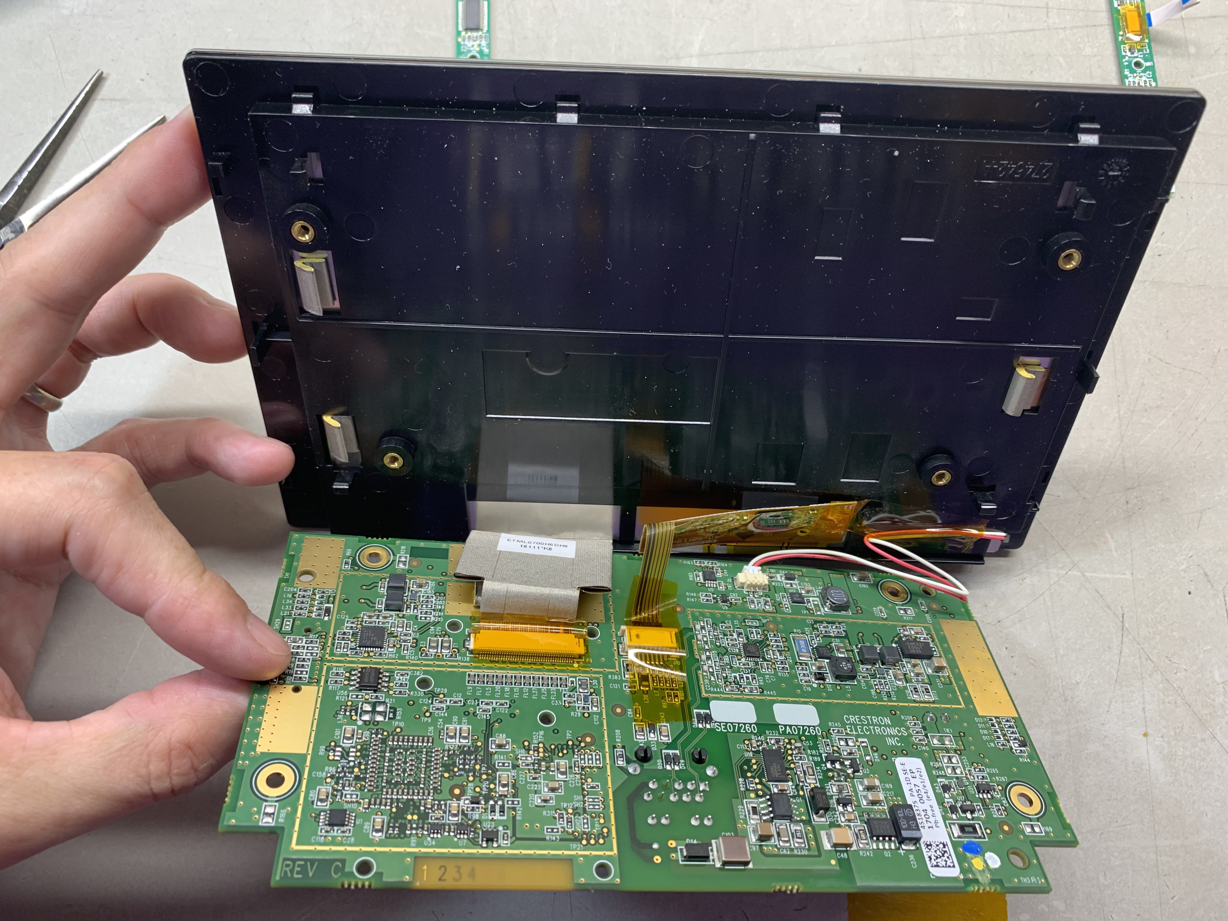
There are four plastic clips that hold the PCB to the back of the display. I used needle nose pliers to spring them aside and release the PCB. Flex them one at a time and you can get them loose.
Remove some of the brown Kapton tape holding the backlight connection down.
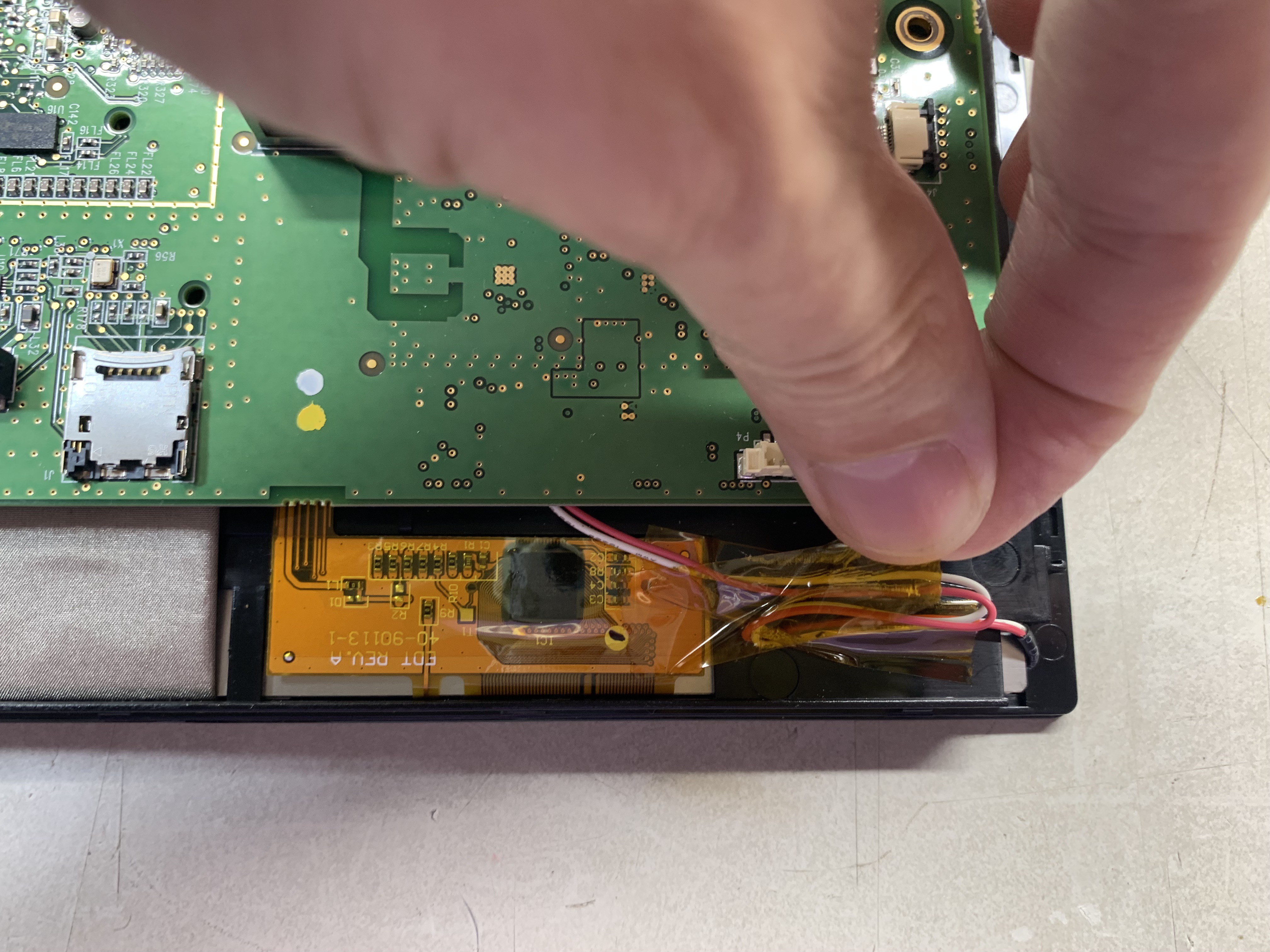
Now you can carefully hinge the PCB down (or display up) to access the three connectors (40 pin FPC for display, 8 pin FPC for touch-screen, and two-pin 1.25 mm pitch connector for backlight).
Carefully remove any Kapton tape holding the Flex connectors down. Try not to stress the flex cables.
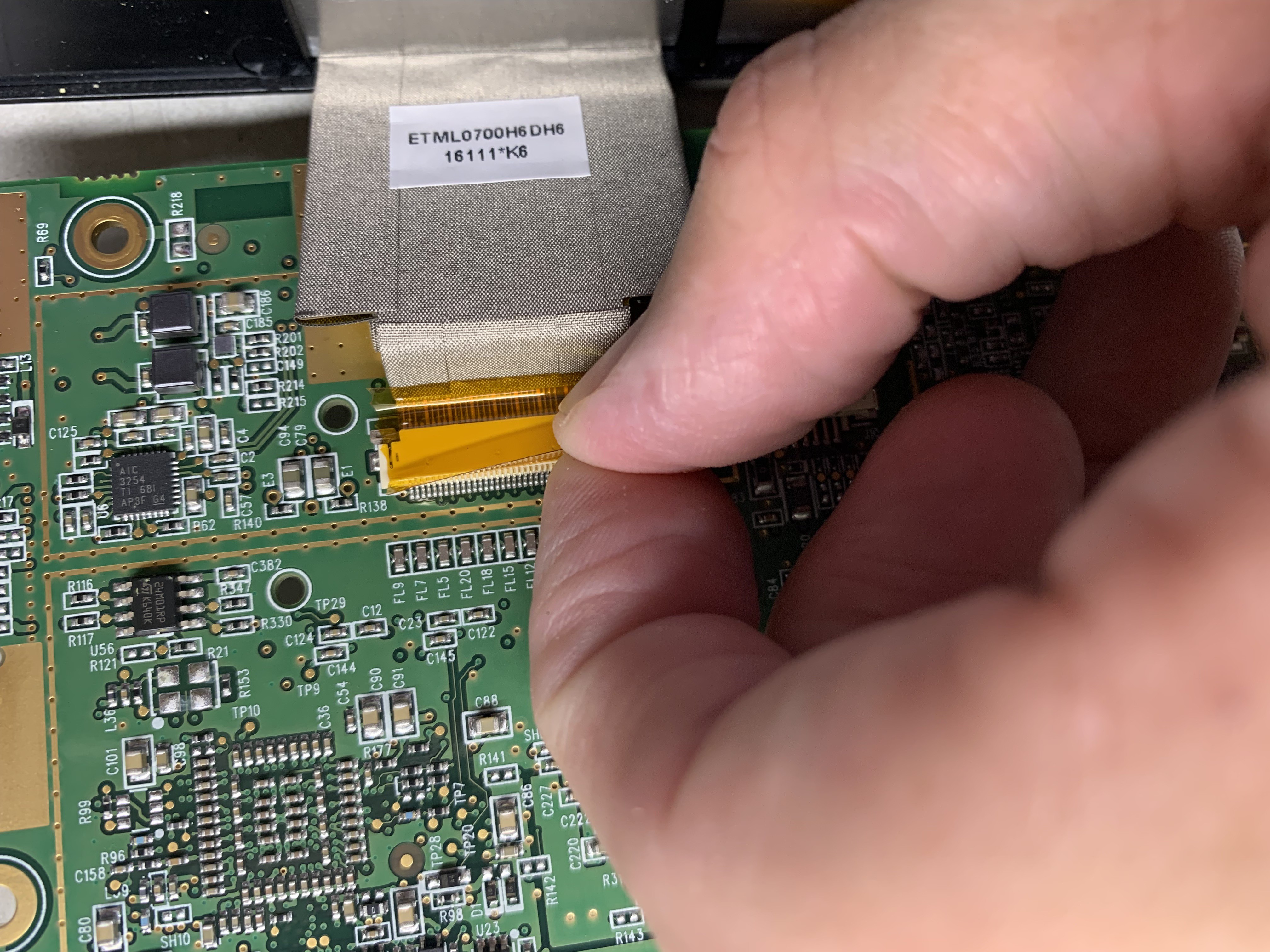
Now slide the FPC connector latches and remove the flex connectors.
Here's the parts laid out:
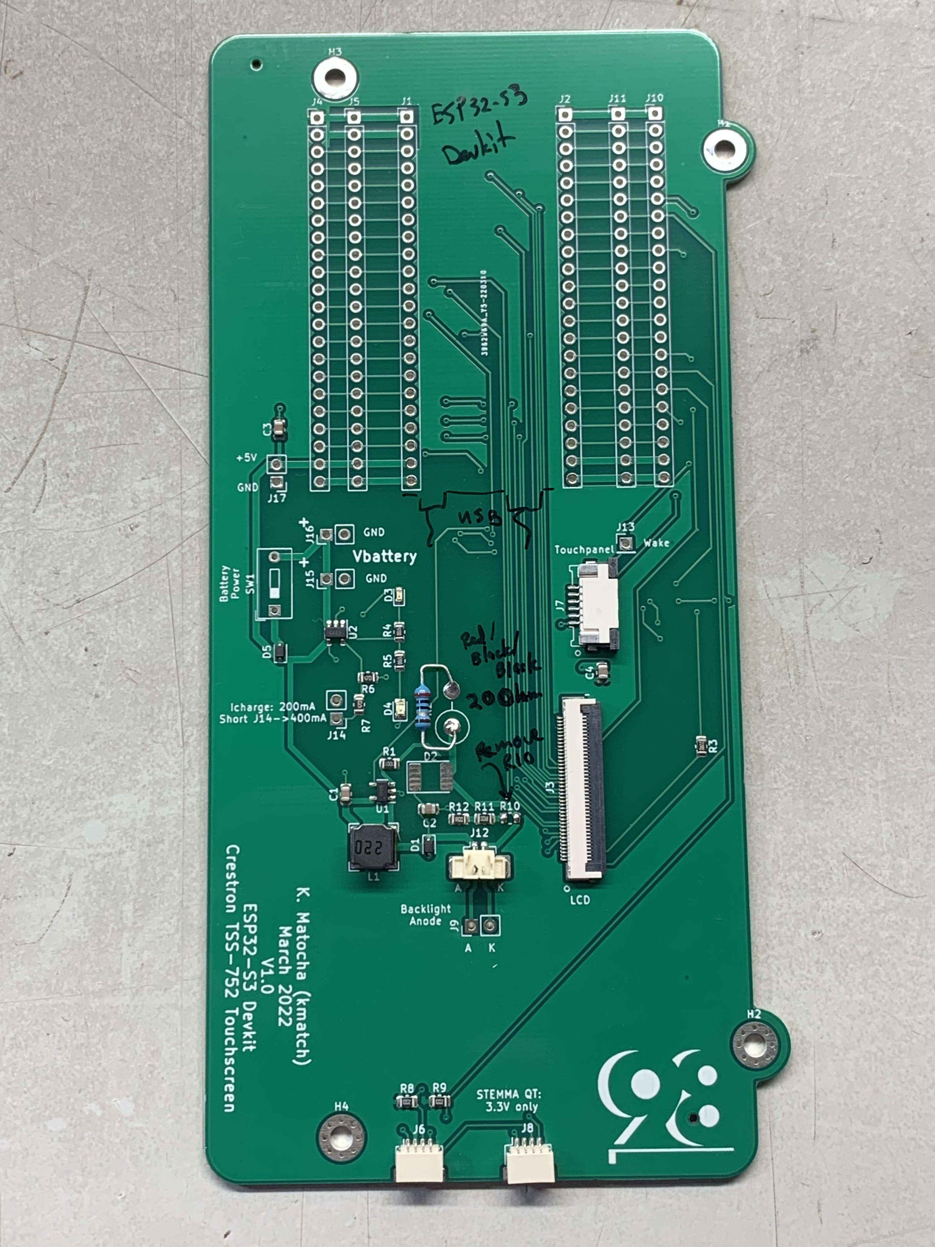
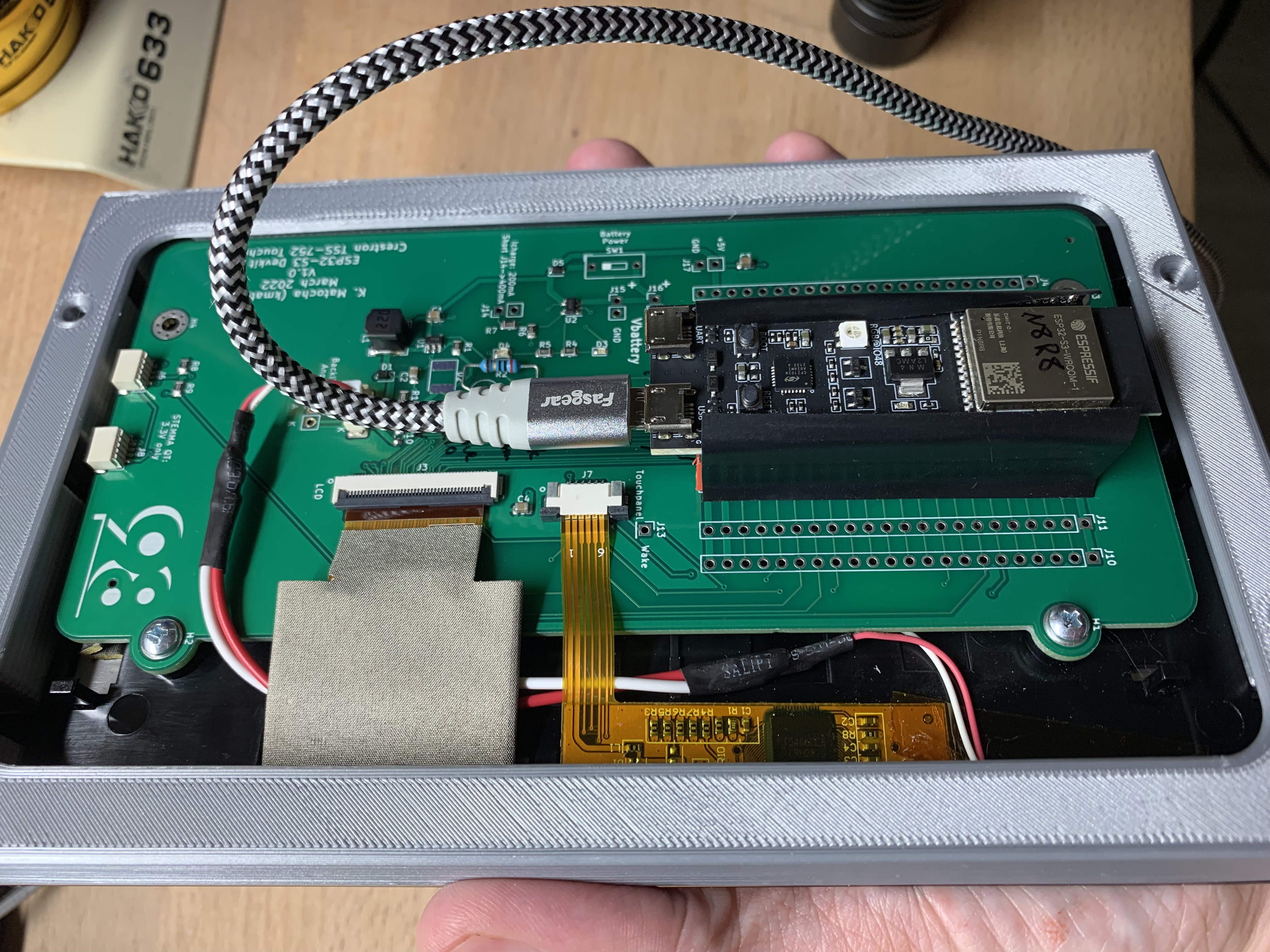
Now prepare your PCB. The original design had too much backlight current. I removed R10 and soldered a 20 Ohm resistor at position R2.
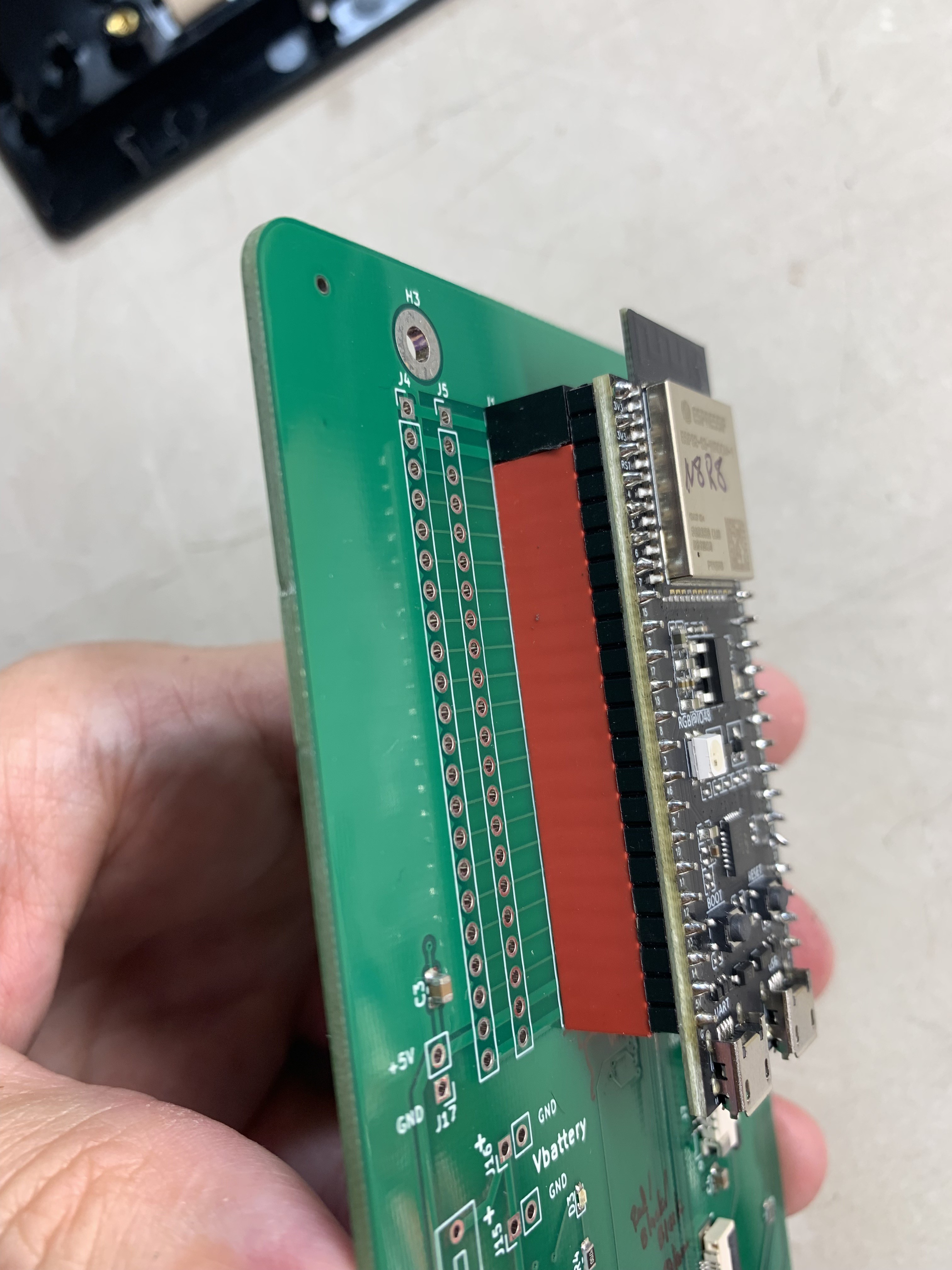
I soldered headers onto the board so that the ESP32-S3 devkit is removable if required. I didn't have 22 pin connectors, so I had to make an extra 2-pin header by cutting a longer header and sanding it to fit. Note the orientation of the USB connectors when install the devkit board. To prevent scratching anything, I put some tape on the headers.
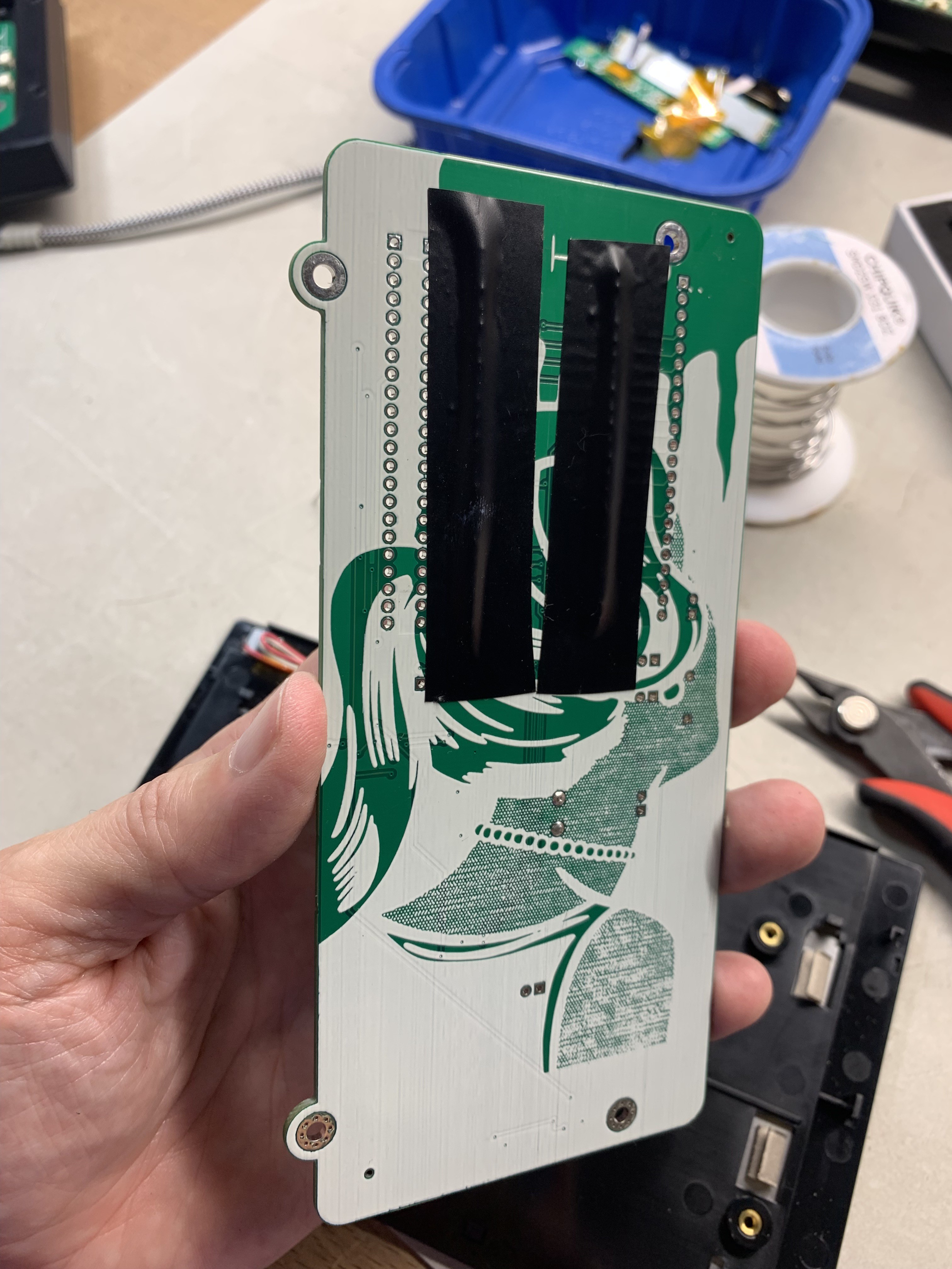
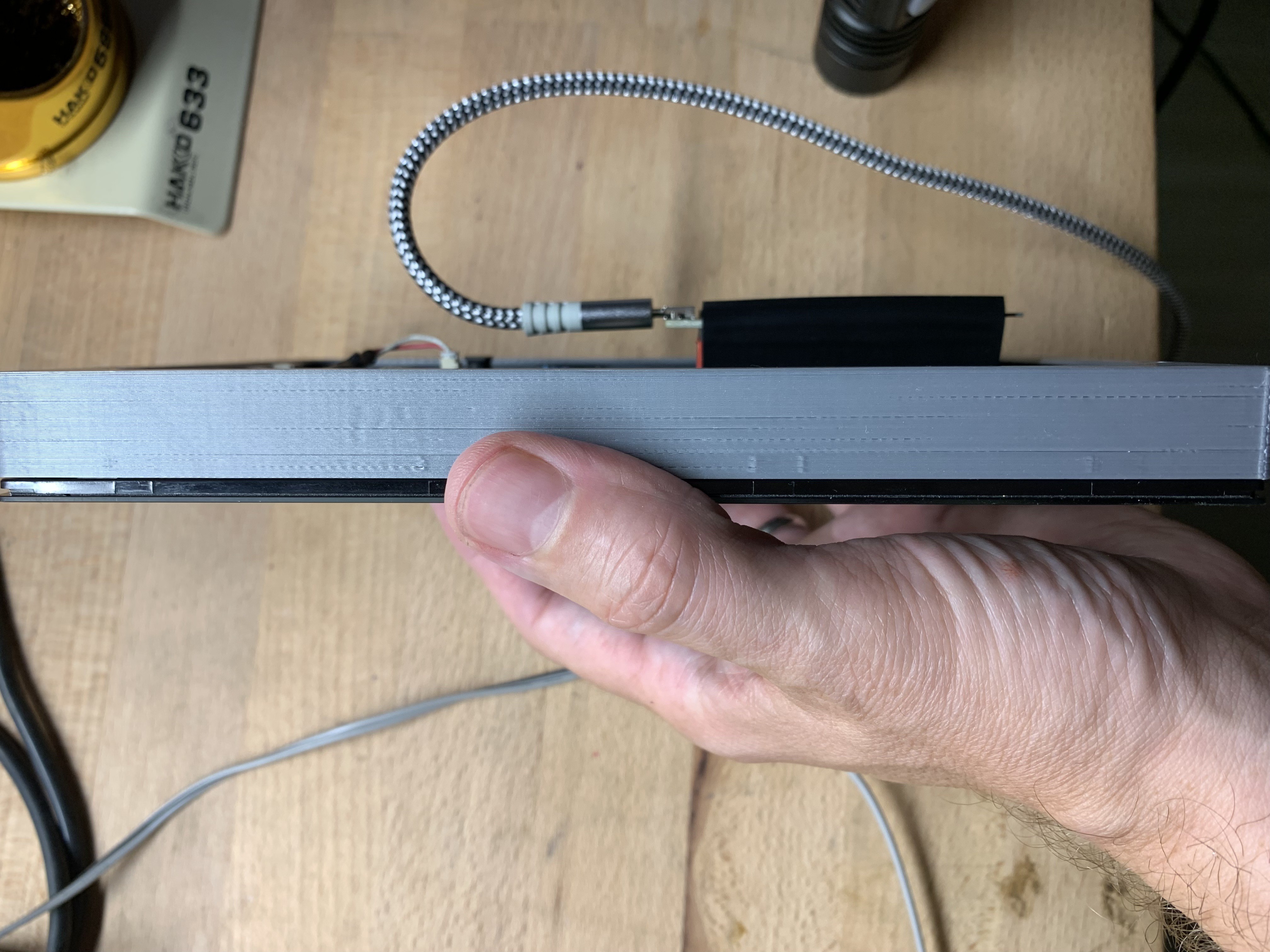
I created a thin 3D-printed bracket to make the unit easier to handle. The devkit protrudes out the back, so I put some tape on it to prevent scratching anything.
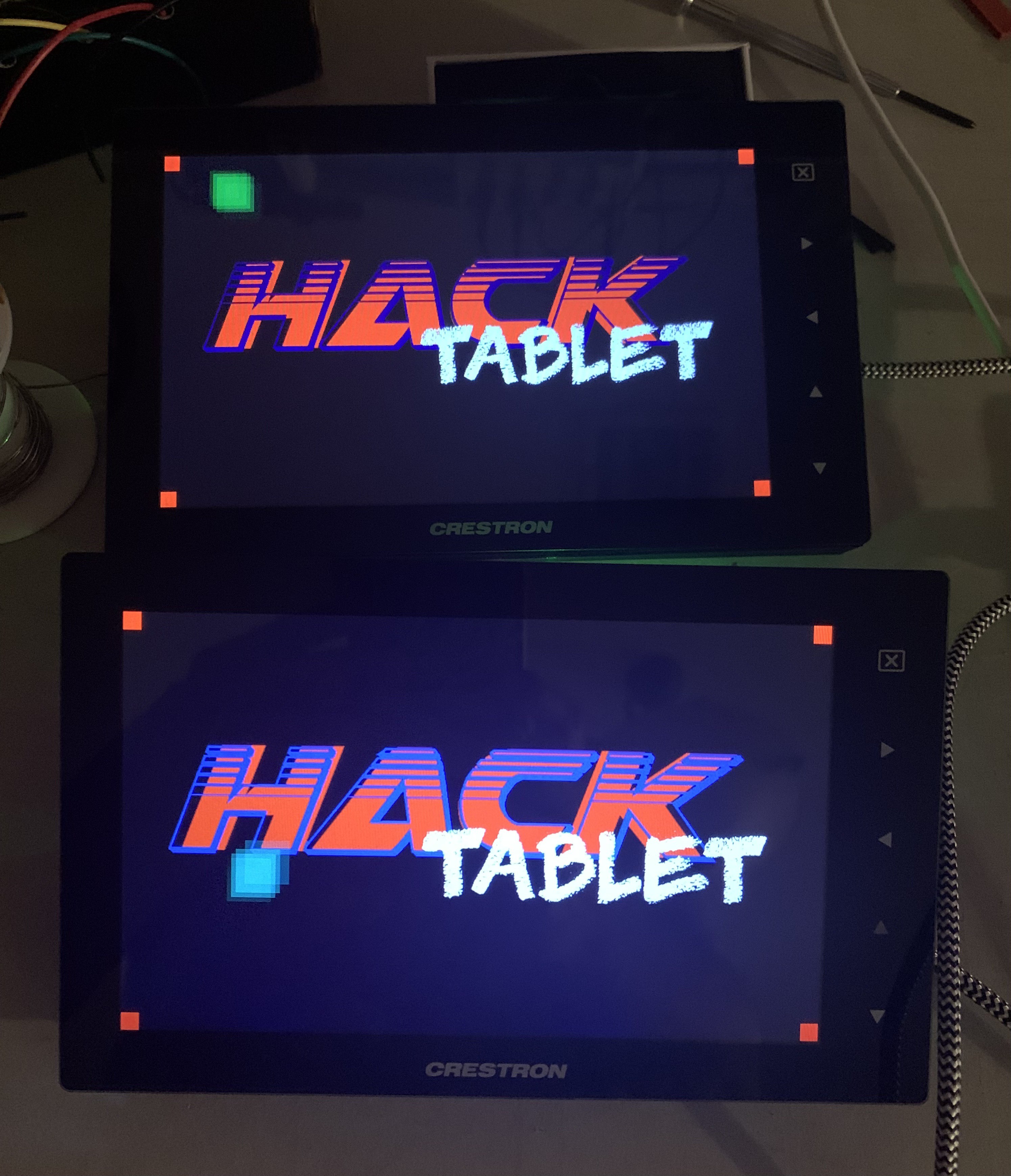
Now there's two working units:
Discussions
Become a Hackaday.io Member
Create an account to leave a comment. Already have an account? Log In.