Close
0%
0%

Screenshot Camera (or Grabby McScreenface)

HaD asked for odd and peculiar? I think I can oblige!

Public Chat
Similar projects worth following
In the category of “Press the any key” and especially for this contest, I build this. A bluetooth connected Brownie six that lets you take a screenshot of your desktop or the active window depending how you orientate the camera. It literally is a wireless screenshot button!

Short demo video below.

Demo

Nevermind the circus. The camera is the project!


The concept

I’m always looking for ways to make interacting with objects (historical ones) easier and enjoyable. Hands on easy access to artefacts is one of the best ways to get people to experience history. So my goal with this entry is to show my peers that interaction with artefacts is not necessarily expensive and complicated. With a solid concept and a clear plan, easy interaction that makes sense is perfectly feasible. That is why I chose to “marry” my experience with making HID devices with my old camera collection. I could have entered my morse key project, LiDAR experiment or even my oddly popular Okudagram interface project  but I wanted to make something specifically for this entry. So this is it!

The build

I chose the six because it has oodles of space inside. It can even fit an entire RPi is needs be. Of course with smaller boards it would be perfectly possibly to fit this inside even something as small as a Olympus Trip, but the dual sight feature on the Brownie was something I wanted to highlight in it’s functionality as a HID device.


(A Brownie can easily fit a RPi with case.. Hint hint hint!)

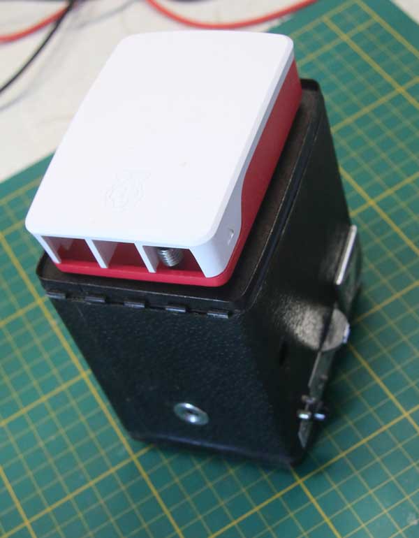
This camera is a permanent part of my camera collection and as such I did not want to alter it in ways that were non-reversible. The main part of the build therefore was to source or make components that would friction fit inside the case without having to alter it in any way. It turned out that a UNO form factor would be a nice fit and I still had some prototype shields laying around so that would be the base. I started out with a 8266 board but that did not have Bluetooth and my serial Bluetooth modules were all incapable of being a HID device so I ordered a ESP32 board.

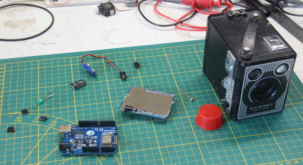
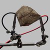
Rougly what I started out with to do the mock up.

For the orientation detection I first selected a six axis motion detection board that worked via I2C. A bit overkill (not that the ESP32 is the bare minimum for being a button!), but I could add future functions to it with certain movements like when you shake it a certain way, it could send a command to make a Polaroid style image for instance. In the end I chose a simple roller switch because I had one and it would be much simpler to implement.

The trigger itself is a photo resistor. It is placed in front of the shutter and it registers when it is open. The sensor is mounted in a piece of end-cap for PVC that is just about the right size to friction fit in the hole in front of the sensor. This friction fit business will be a running theme! I potted the sensor with some old paint to keep lights out from the back and that works a treat.

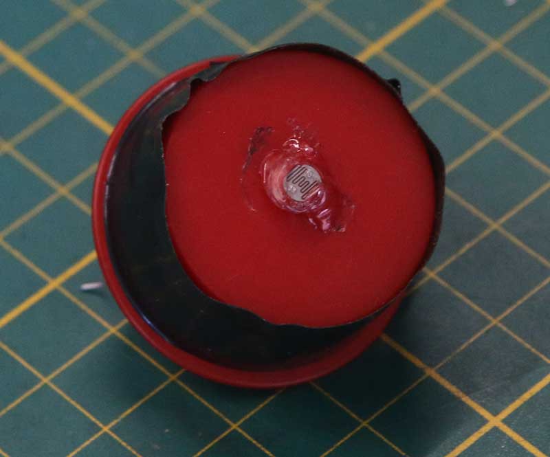
Yes! Hotsnot!.. Also podded with outdoor paint! Sue me!

The unit works with a 9 volt battery that is logged in at the top of the case. A piece of MDF with fabric keeps it snugly in place. A led at the back indicated power-on, Bluetooth connected and shutter released. All not rocket science.

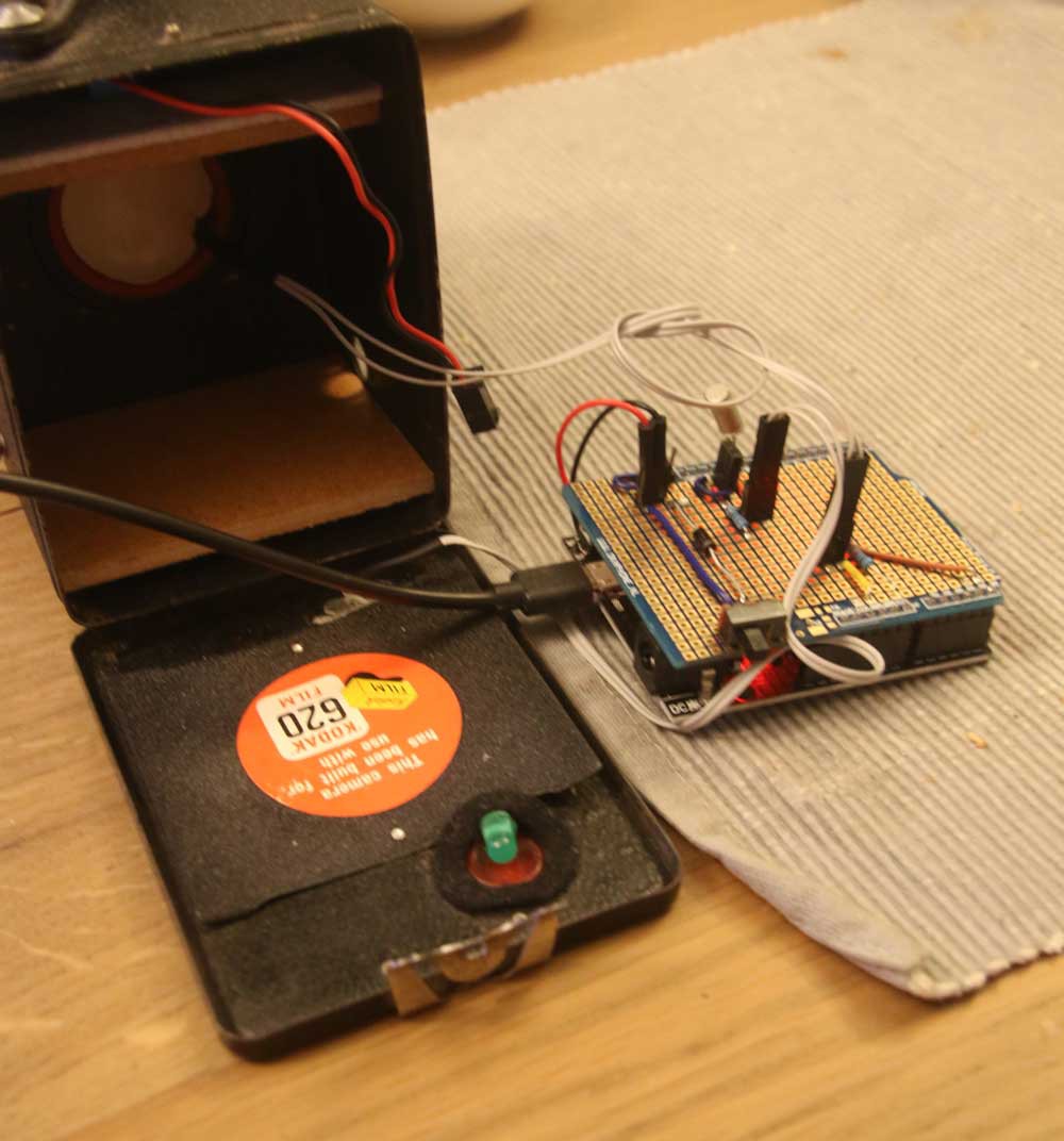
Cameras like these are steal boxes. There are a few holes like the lens and mine has the winding spool missing, but there isn’t a lot for radio signals to get to to the outside in this faraday cage. It turned out that is was not a problem on my laptop. It could see the device perfectly and it never failed, but on the RPi desktop that I wanted to use for the demo, it did not work out as well. As a result I had to make en MDF backplate to make it work. This did work in my favour as I could now make a hole for the on/off switch.

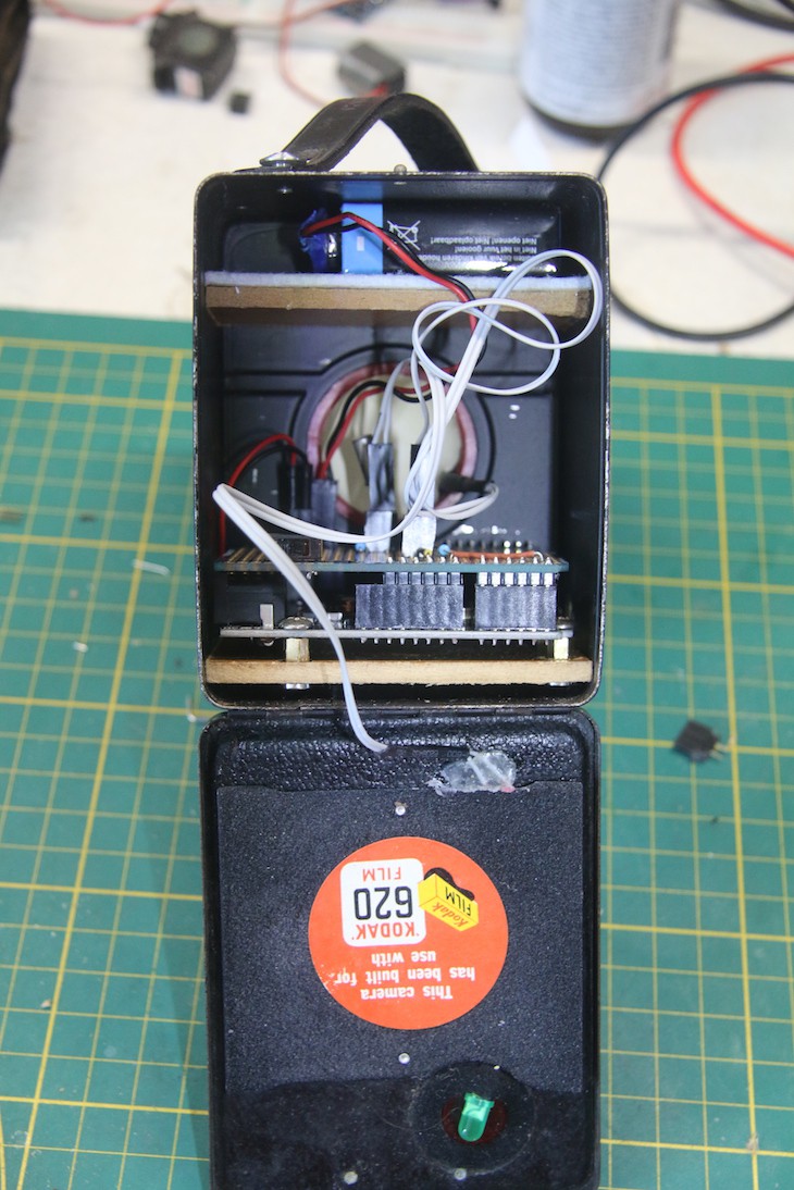
The whole device assembled, albeit with the original backplate that has temporarily been replaced by a MDF insert.

The Software

This is not a complicated project. The sketch for the ESP32, available below, does a couple of things. Check connection, check the sensor, check orientation and send keyboard commands for the computer in order to make a screenshot.

On the desktop side, I made two simple bash scripts (available below) that uses scrot to...

Read more »

openboxconfig.txt

The config I added to openbox keyboard shortcuts. This file is located at : /etc/xdg/openbox/lxde-pi-rc.xml

plain - 333.00 bytes - 06/16/2022 at 18:47

Download

screenshot_window.sh

The script to grab the focussed window and open it on Raspberry Pi OS.

x-shellscript - 51.00 bytes - 06/16/2022 at 18:46

Download

screenshot.sh

The script to just grab the whole screen and open it on on Raspberry Pi OS.

x-shellscript - 48.00 bytes - 06/16/2022 at 18:46

Download

GrabbyMcScreenFace.ino

Basic sketch for the Screenshot Camera.

ino - 2.70 kB - 06/16/2022 at 15:41

Download

  • 1 × Brownie Six camera Or any camera that can house some components.
  • 1 × ESP32 development board In this case UNO form factor.
  • 1 × Photo resistor
  • 1 × Led Fiber Optics / Emitters
  • 1 × Protoboard

View all 13 components

  • Potential variations

    Timescale06/28/2022 at 15:17 0 comments

    The Brownie six was the obvious choice because of the space it offered for the components, but having looked at my camera collection, I see no reason why this concept even with a bit more functionality would not be perfectly possible. I had some thoughts on that.

    The next easiest option would be to use a leaf shutter which are mostly located in the lens and not at the back. In a typical 35mm body, the spaces for the film canister and spool offer more than enough space to place a battery and a small ESP32 board with the necessary components.

    I would discourage using curtain shutters cameras as these are easily damaged, but even with metal blinds, the backing plate present in most SLR's and rangefinders would probably have to be removed for the light sensor to clear the shutter. In many cases this would be a destructive mod. Another potential suitable body for this mod would be something like an Agfa Clack.

    Adding a second roller switch would enable for 3 commands to be sent. For the Brownie this does not make a lot of sense, but for an SLR, rangefinder or simple point and click camera with a viewer at the back, this would be perfectly reasonable.

    Shutter speeds that work will depend on the lens type and lighting conditions, but with some crude experimentation, I found that under normal lighting conditions an eps8266 was fast enough to catch the signal from the light sensor within 125th of a second most of the time. In slightly darker settings 500 works pretty good as did "bulb" on various cameras. I the end you can go as slow as you want to make it work because it does not really matter for the end result! It is more about the sound that you want from the camera if anything.

    On a separate note, I have seen a lot of nice new entries in the competition using ESP32 BLE modules. Got a lot of inspiration from those and perhaps the ESP32 is my new favourite controller!

  • Contest request

    Timescale06/16/2022 at 18:54 0 comments

    In the unlikely event that this project does win some price, I would naturally gladly have the honor, but I would like HaD and Digikey to donate the amount granted to a humanitarian cause for the people of Ukraine rather than giving it to me.

    I also encourage other participant to offer their potential price as a donation for that good cause. If a lot of us request this, the odds of us making a helpful contribution to that horrid and terrible conflict will certainly increase.

View all 2 project logs

  • 1
    Choosing a camera

    A box camera is an easy choice because of the space it has inside and how simple the mechanics are. But there is no reason why this type of input device could not be implemented in other camera bodies. The iconic Agfa Clack series should do nicely for instance, but there is no reason why you could not do this in a typical 35mm SLR camera as long as the ESP32 board is small enough to fit somewhere.

    I considered a range of cameras for this project. The Braun super vier, Zeiss icon iconmatic-A, Olympus Trip and even the venerable Pentacon six. In the end I went for the Kodak Brownie Six-20 E, so a six it was! But there is no reason why this could not work in other bodies.

    This is just a part of my.... problem! There is more...

    The Brownie was chosen for the simple reason it had a lot of space and the dual sights as a function spoke to me, but other functionality and symbolism would be equally apt when used in other cameras. I can imagine an old camera body being a remote for a digital camera for instance. Creating the illusion that an old camera is taking a digital picture with the actual camera somewhere in the distance.

  • 2
    Friction fit

    This entire build is non-destructive and completely reservable. The key to doing that is friction! Every component for this hack sits very tightly in its place and does not move. For extra security you could add hot-glue, but I have not needed that to keep things neatly where I want it.

    The sensor is mounted in a cap which, with a piece of tape, fits into the well of the lens. This solution will of course vary with the body you choice, but for the Brownie, this 32mm pipe cap seems to be a match made in heaven.

    The board and battery are both constrained by carefully cut pieces of MDF board. They just tuck into place and do not move. Again, depending on the components you have, this solution will vary.

    The backplate is also a carefully shaped piece of MDF that just friction fits into place. It exposes the status led and the power switch. The original backplate can still be attached to the body, but being a steel faraday cage, not all clients will be able to connect to the device.

    This way, no holes or other alterations had to be done to the camera and it can easily be restored to original conditions.

  • 3
    Electronics

    For the electronics I used a proto board shield I had lying around. It really is quite simple. If you choose another microcontroller form factor you'll need other solution, but it is not at all complicated.

    The board takes 9volt from the battery and sends it to the ESP32 board via a switch. It also connects the photo resistor to one of the analog pins, the roller switch to a digital pin and the status led.

    I added a diode for the input power. I do not think it is necessary, but I did it anyway. The roller switch is just a switch so it needs a pulldown resistor if your development board does not have these internally. The ESP32 does!

    The photo resistor does need a resistor (10k Ohm) as does the led of course ( I used a 100 ohm which is fine for 3.3v i believe)

View all 5 instructions

Enjoy this project?

Share

Discussions

Gradivis wrote 04/08/2023 at 09:39 point

Love this! I'm always thinking of ways I can repurpose non-functional film cameras, but this is a new level :D

  Are you sure? yes | no

Your Friend Zero wrote 06/20/2022 at 23:44 point

Really enjoyed your video! all the dif hids leading up the the grabby reveal was a nice touch.

  Are you sure? yes | no

Timescale wrote 06/21/2022 at 01:35 point

Thanks, it was a lot of fun coming up with the concept and making the media. I liked your BLE watch keyboard a lot as well. I would not mind doing something like that with my LCARS interface concepts.

  Are you sure? yes | no

Similar Projects

Does this project spark your interest?

Become a member to follow this project and never miss any updates