 Eric Hertz
Here, since I'm usually so disorganized in my logs, maybe a
Table Of Highlights:
Intro
Reversing For Fun And Profit - Why I Like To Do It --Ziggurat29
Z80 Hackery With Ziggurat29 - A "Brief" History --Eric
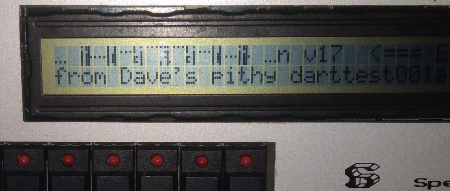
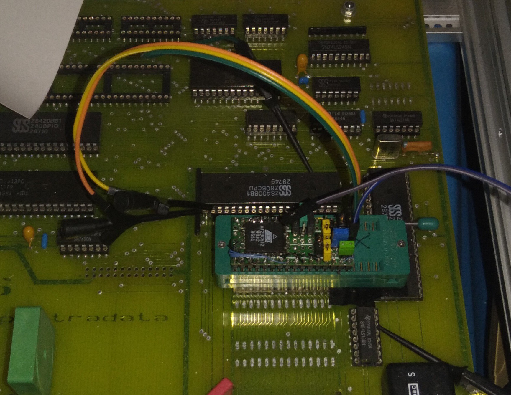
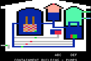
Spectradata SD70 - Eric's Interest
Reverse Engineering
Spectradata SD70 - The Beginning
(Surely more logs than listed here)
BIG NOTE:
If you're reading the logs through the logs-list, rather than one by one, you're missing quite a bit, as many of our discoveries, both related and unrelated to the log itself, wind-up in the comments. Heh... whatcanyado


 Jorj Bauer
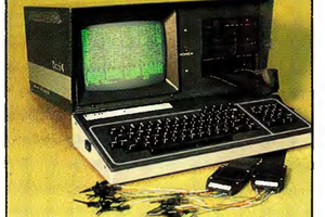
 furrysalamander
Long ago and far away I knew a guy who was developing a CPU in-circuit emulator. Too long now to recall whether he used a Kaypro or an Osborne. No matter. He coded it all in hex. Seriously. I don't remember whether he had a name for it at that time. Would have been roughly 1983.