 Eric Hertz
So, imagine a regular-ol' drill-press...
(I'm no expert, here, so much of this is based on a handful of experiences and a bit of imagining)...
You've got a lever which moves the chuck/drill up and down...
When you hit material, the lever gives you "force-feedback" indicating many factors.
There's resistance from the material...
First of all, you can tell when the material has been hit... besides just visually... Aside from that, feedback through the lever can tell you quite a bit more, including: Maybe the material really just doesn't like to be drilled, and you should speed-up/slow-down the bit's rotation to accommodate. Maybe you've got to apply a ton of downward-force, and that's just how it is... In a case like that, one can sense whether the force-necessary is more than the drill-press can handle... stepping back the force and speeding up the bit may help.
Resistance from the bit... Maybe it's dull, etc. This too can be sensed, to some extent, from the "feedback" in the lever.
There's a completely opposite-effect... What when the bit snags in soft-material, cutting really smoothly, to the point that the bit is sucked into the material? This can be to your favor, or it can cause it to snag/stall when it's tried to grab too much material. Or, worse, the material itself might be ripped out of its vice, and spin around, causing all sorts of damage to equipment and people... This effect can be *felt* by the skilled-user, before it goes awry.
I'm sure there're plenty more sources of "feedback" skilled drill-press-users can detect merely by watching/understanding the process, and from *feeling* the process (through the lever).
-----------
In #Big Ol' Modular CNC, I've been building a *modular* CNC-system (within my supplies/skill-set, don't laugh!)... Wherein axes can be added-and-removed as-needed. The ultimate goal might be a 3-axis router-system, ala a Mill... But there's also lathes, and other things which can be accomplished with even fewer axes.
The *simplest* case may be a "one-axis" machine... Like... A drill-press.
And... So far (after well over a year), I really only have one axis completed.
I can't quite wrap my head around the usefulness of a CNC-drill-press...
But, I can wrap my head around a drill-press which might e.g. have higher precision than the roughly 1:1 ratio provided by a directly-connected lever. And I can wrap my head around the idea that some materials might be harder to drill than a lever, alone, can provide the force necessary for...
--------
So, here's the idea:
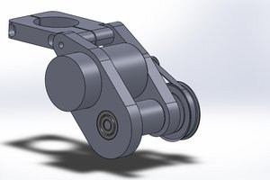
A motor-driven axis controls the displacement of the drill. This guy will be screw-driven, maybe even gear-reduced, such that the motor can provide a lot of force over a very small displacement.
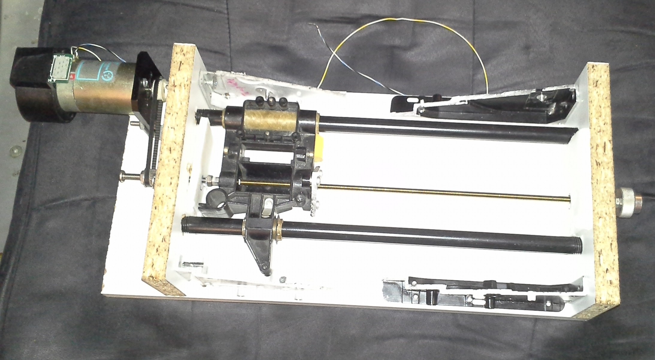
A hand-lever controls the position...
The lever will be attached to a rotary-encoder... So, e.g. one "tick" of the lever's rotary-encoder might correspond to 0.1mm of displacement of the drill.
Pretty simple, right?
--------
But here's the kicker:
I want force-feedback...
--------
Well, consider this... a normal drill-press has a springy-mechanism, pulling it back to the full-up position, when released... Or, at the very least, not allowing the weight of the drill (or lever!) to pull itself down.
But, since the lever is physically detached from the drill's axis, there'd be nothing stopping it from "falling" to the lowest position, telling the drill to move downward at the highest rate possible as soon as the lever's released. Not good.
So, even without force-feedback, it would be useful to have some sort of "resistance" on the lever to prevent its falling on its own. And, maybe even, a "springy"-factor to cause it to pull back up when released.
How can this be accomplished...?
Well, a spring, obviously, and some felt-pads to resist motion... But none of that helps force-feedback.
----
The idea, here, is to attach a *motor* to the lever.
This motor can, then, handle not only force-feedback, but *also* things like "friction" and "springiness"...
-------
Feedback-loops are not at all...
Read more »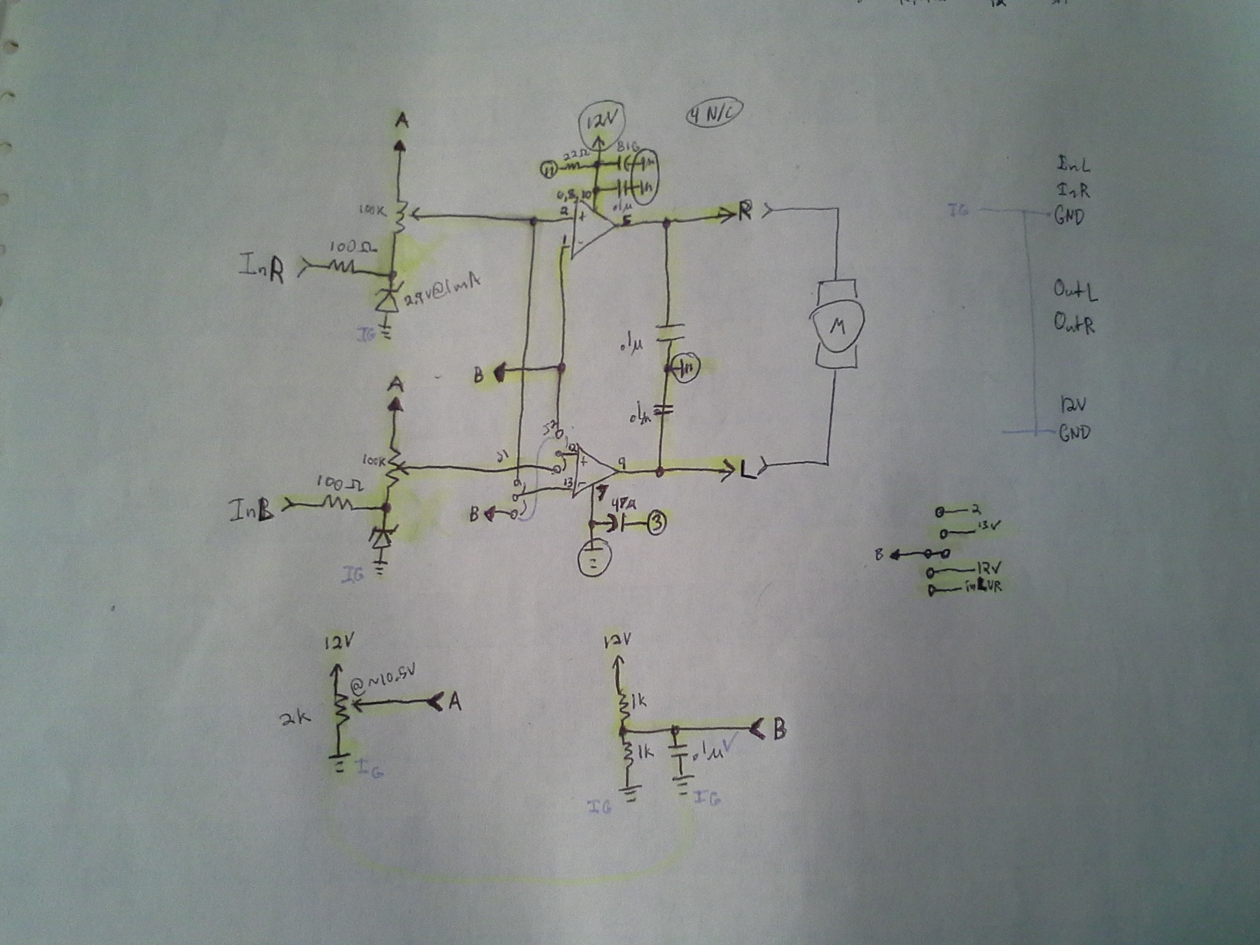


 Chaz
Chaz
 Frank Herrmann
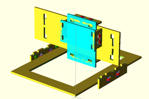
I like this idea. I can imagine using it from another room with a camera system so when the improperly-clamped workpiece gets thrown across the room, I'm not there to get hit :-)