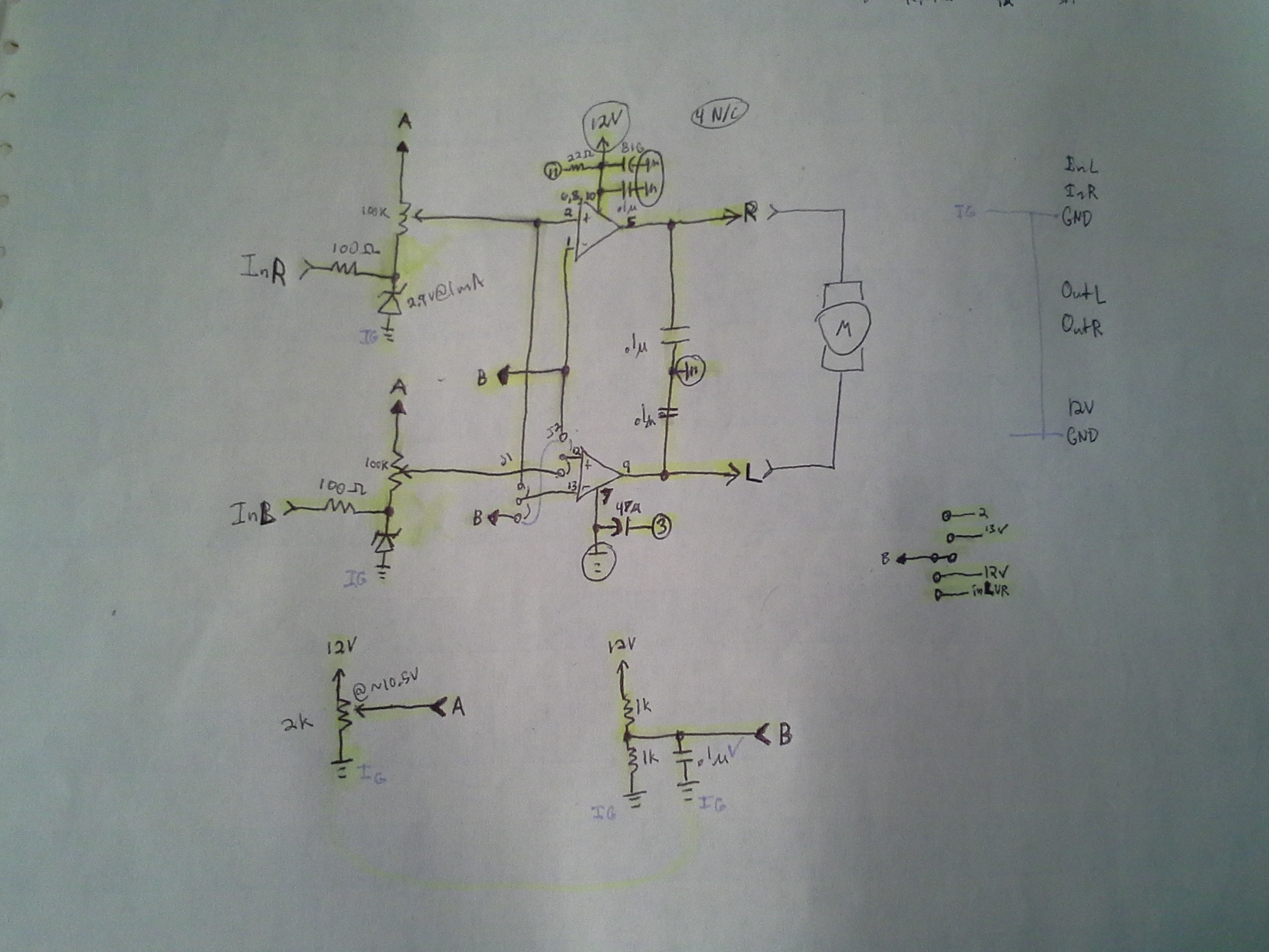
Probably burried in the last log are a few thoughts...
Locked-Antiphase PWM is difficult to set up with a "reset-default". How's one going to generate a 50% duty-cycle to stop the motors when the uC is being programmed and its PWM outputs are floating...?
Among other reasons, the solution I chose was to forgo Locked-Antiphase, in favor of two inputs, one for PWM and one for DIR.
If you think about a regular H-Bridge, there's two inputs and two outputs. Driven digitally (high or low) the outputs essentially follow the inputs. A logic-high on one input will result in that side of the motor-winding being driven with the high motor-voltage.
So, then... one way to drive those two inputs is to choose one input as DIR and the other input as PWM. (Annoyingly, when DIR is reversed, the PWM value must be inverted, e.g.25% duty-cycle for 25% power-output needs to be 75% duty-cycle for 25% power-output. But that's not a big deal).
So, then... for a "reset-default" that won't cause my motor to spin at full-speed when the inputs float, simply add pull-resistors to the inputs... both to the same level.
SIMPLE!
Coded it all up, less than 100 extra bytes... Awesome!
---------
Yeah, but... My motor-driver/H-bridge is a bit of a wonkey-experiment...

High-power op-amps (audio-amplifiers) are used as, essentially, comparators. The inputs are analog, not digital, and they've comparatively low-impedance.
Reasonable-valued Pull-resistors, alone, probably won't drive enough current to do this.
OTOH, took me way too long to figure this out, but *maybe* I can change the values on the 100K potentiometers such that the "floating" inputs would result in high (or low?) output.
Anyways, I'll have to look into all this a bit further. I still think pull-resistors, at the uC-output, are a good idea... (This isn't the only motor-driver I might use, and it's a separate board). So... ToPonder, but not tonight/this-morning.
 Eric Hertz
Discussions
Become a Hackaday.io Member
Create an account to leave a comment. Already have an account? Log In.