 Eric Hertz
BIG TODO/WARNING:
WORKING WITH MOTORS CAN BE DANGEROUS: BE CAREFUL!!!
-------------------------
Realized upon drawing up the schematic (referencing an old one), that there's a dangerous problem with how I intend to drive the motor... There are dangerous cases where the motor will run at full-speed/power, that have nothing to do with my programming-skill!
-------------------------
Specifically, in this case:
I plan to use Locked-Antiphase PWM control of the motors...
(Locked-Antiphase is where PWM-value of 0% results in full-power in one direction, 100% is full-power in the other direction, and 50% duty-cycle stops the motor).
Can yah guess the problem...?
When PROGRAMMING (or in reset, or worse, if the uC fails), the pin driving the H-Bridge's PWM-input will be floating. It *might* float near ground or near V+... Thus, when programming, the motor might run FULL POWER/SPEED in one direction or the other!
Previously, I used separate outputs for PWM and Direction, so it was easy to tie a pull-down resistor to the PWM pin, such that when programming (or the pin was otherwise floating), the motor-driver would be disabled. Not the case with Locked-Antiphase. WHAT TO DO...?
This is DANGEROUS in this case!
- The drill-press motor could slam into either end, at full-power.
- Don't have your fingers anywhere near the moving parts when programming!
- Don't have anything on the work-bed that might fly across the room!
- Don't have a drill-bit in the chuck that could break and fly across the room!
- Make sure your system is strong enough to handle these sorts of disasters!
- The handle/lever-motor could slam into either end, at full-power!
- (Is there an "end-stop" in this design? Or will it spin around at full-speed?)
- Don't have your fingers anywhere near the moving parts when programming!
- Don't have anything near the lever's path that might fly across the room!
VERY IMPORTANT when working with high-torque motors:
(This list is *by no means* all-inclusive! Think For Yourself and Do Research, and even still, consider yourself a contender for The Darwin Award!)
- ALWAYS install an emergency-cut-off switch!
- This should *PHYSICALLY CUT THE POWER TO THE MOTOR* not go through software or even the H-Bridge
- This should have a large easy-access button which can *only* be turned-OFF in a frantic reach
- Install end-stop detectors!
- (AKA "Limit Switches")
- Do-so at *both ends* *even if* you don't need to *measure* the end-stop positions, nor move to 'home'
- These should *physically cut the power* to the motors, as in 1a.
- Consider what happens when the software/circuitry is non-functional, and design with this in mind!
- This can occur e.g. when:
- The microcontroller is in reset (or programming, or failed due to unintentional shorting, static-shock, etc.)
- power is lost to the controller-circuitry, but high/motor-voltage remains
- Install pull-resistors
- Install a watch-dog *circuit* as well as watch-dog *software*
- I'm losing steam. Think about that Darwin Award.
- This can occur e.g. when:
- DURING software-devel and/or during circuitry-assembly:
- It's *EASY* to accidentally reverse-polarity either the motor or the encoder... Either one could result in the motor attempting full-power back to its desired-position!
- It's *EASY* to accidentally reverse-polarity either the motor or the encoder... Either one could result in the motor attempting full-power back to its desired-position!
-------
So, I'm working on 3b...
Problem is, I'm out of motor-drivers with PWM/DIR inputs.
In fact, I'll be using two different motor-driver/H-Bridges for this project, and planned to drive them with the same signals...
[Insert a lot of rambling, here, and maybe a solution or two I hadn't foreseen before writing this]
(I'd been working on a third motor-driver circuit, for a separate project. This driver one *only* has locked-antiphase as an option... Funny it hadn't occurred to me, until now, the potential for Darwin Award Winnings!)
The first H-Bridge, in this project, has the PWM/DIR option as well as Locked-Antiphase, and ALSO has a BRAKE input. So, with locked-antiphase, I can pull its BRAKE pin *high*, and floating won't be a problem.
The other H-Bridge also has Locked-Antiphase as an option... so that seemed like the obvious choice. But, of course, I've yet to think about how to do a simple hardware-hack to assure 50% duty-cycle when that output's floating (maybe a 555? Maybe I should put that *on* the motor-driver circuit-board? Maybe just a relay that cuts the power...?).
This second H-Bridge *also* has the option to be controlled with a third PWM-mode... I don't know what it's called, but you basically tie one input high/low, then PWM the other input, for one direction. For the other direction, you *swap the pins*.
(Rereading: Wait a minute... can't I just use the high/low input as a direction-input??? HMMMM)
This second option is a bit more difficult on some uC's where PWM-outputs are limited in numbers. So, I tend to avoid using it, and, again, it's not an option with the first. The gist, then, would be to use *two* PWM-outputs, and drive one at 0% or 100% while driving the other at your desired duty-cycle.
The ATtiny861 I'm using (due to supplies-on-hand) has several PWM outputs (six! sorta) so that's not a *huge* limitation. Those outputs are in pairs, "complementary" outputs, where essentially one is the opposite-polarity of the other, which doesn't help the "floating" case...
(Rereading: or does it...? Sheesh.)
Though, there are a few more options than merely complementary-outputs (including Dead-Timers, which assure they don't swap-signs at the same instant, and a PWM6 mode designed for BLDC control). So, there're definitely options... but it's a bit wasteful of a design if I decide to use less-capable uCs for later projects.
I'll have to think about this some more... If the high/low input could be used as a direction-input... or even if I use the complementary outputs... then all I need to do is pull both pins to the same value (via resistor). Bam.
The first case (high/low input = DIR) *essentially* PWM/DIR input, except that when you swap the DIR sign, you also have to invert the PWM duty-cycle (right?)... Might go with that one... Got some thinking to do...
----------
Oh, "schematics"... Not yet complete...
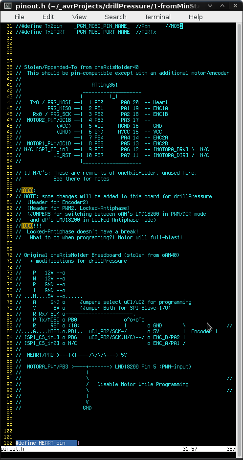
Apparently I'd been *using* the "oneAxisHolder" off-n-on for *various* projects, for years... and never drew up schematics/pinouts in a single location... Was "fun" digging through all the source-code and tracing it out on the proto-board to figure it all out again, years later. So, what you see above is basically that, with some TODOs for this new project, because, mostly, building an entirely new circuit-board isn't really in my mindset, lately.
So, in figuring out whether the "second" motor-driver will work with pseudo-PWM/DIR, this may be helpful... from my ol' #Random Ridiculosities and Experiments wherein I'd been using an audio-amplifier chip as a motor-driver.
(The "Locked-Antiphase-Only" circuit I'd been working on was based on the TA8251AH 4-channel BTL audio-amplifier... And, lo and behold, it has both a "standby" input and a "mute" input, so pull-resistors should work!)
Discussions
Become a Hackaday.io Member
Create an account to leave a comment. Already have an account? Log In.