Somehow, I’ve never actually used a rotary encoder in a project until now. Since I’m not too familiar with this input I thought I’d do a quick project log for my findings.
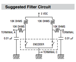
The recommended configuration for the rotary encoder is shown below. When the rotary encoder knob is turned, the switches (seen below) pull terminal A/B to terminal C (GND). Depending on the which direction the knob is turned, terminals A or terminal B will be shorted to terminal C first.
An example for turning left and turning right is shown below. This circuit mirrors the recommended layout shown above (debounce circuit). When turning clockwise (CW) channel 2 leads, and when turning CCW channel 1 leads.
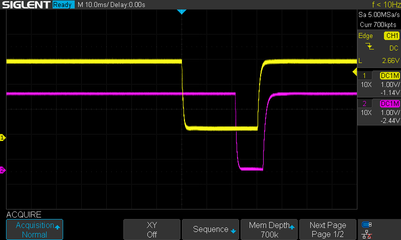
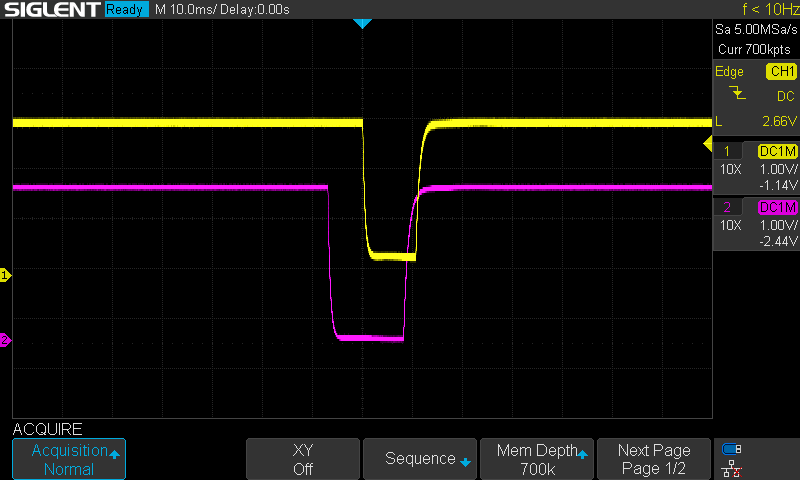
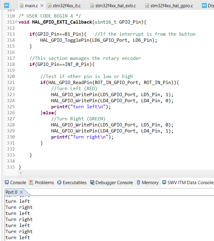
To decode the turning direction in firmware, I have an external interrupt setup on one of the output terminals (either A or B). The callback function executes on the falling edge of channel 1. If channel 2 is low, then the knob was turned CW, else it was turned CCW.
Discussions
Become a Hackaday.io Member
Create an account to leave a comment. Already have an account? Log In.