 Emilio P.G. Ficara
The ESP-01 WiFi module was the first one I used, many, many years ago. It came with a firmware version that allowed you to start working using AT commands. There was no Arduino version yet, so early experiments were all based on using an external micro, which used the powerful (and low cost) WiFi connection capabilities of the module.
Now things have changed. A lot! With the Arduino development environment it’s possible to create so many applications using only the ESP-01 module, properly programmed (no longer with AT protocol). The beauty of Arduino is that it runs on both Windows and Linux and this makes development really possible for all enthusiasts. The only downside of the ESP-01 module is the very limited I/O lines (note: a new 'F' version is available now, with the same name, but much more I/O; it looks almost like the “old” ESP-07). So I thought of making my own I/O expander connected on the two pins of the TX and RX serial port. Here is what came out:
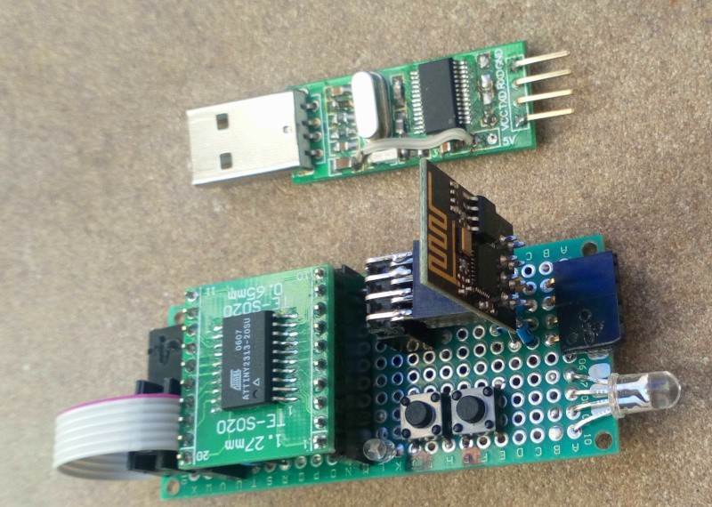
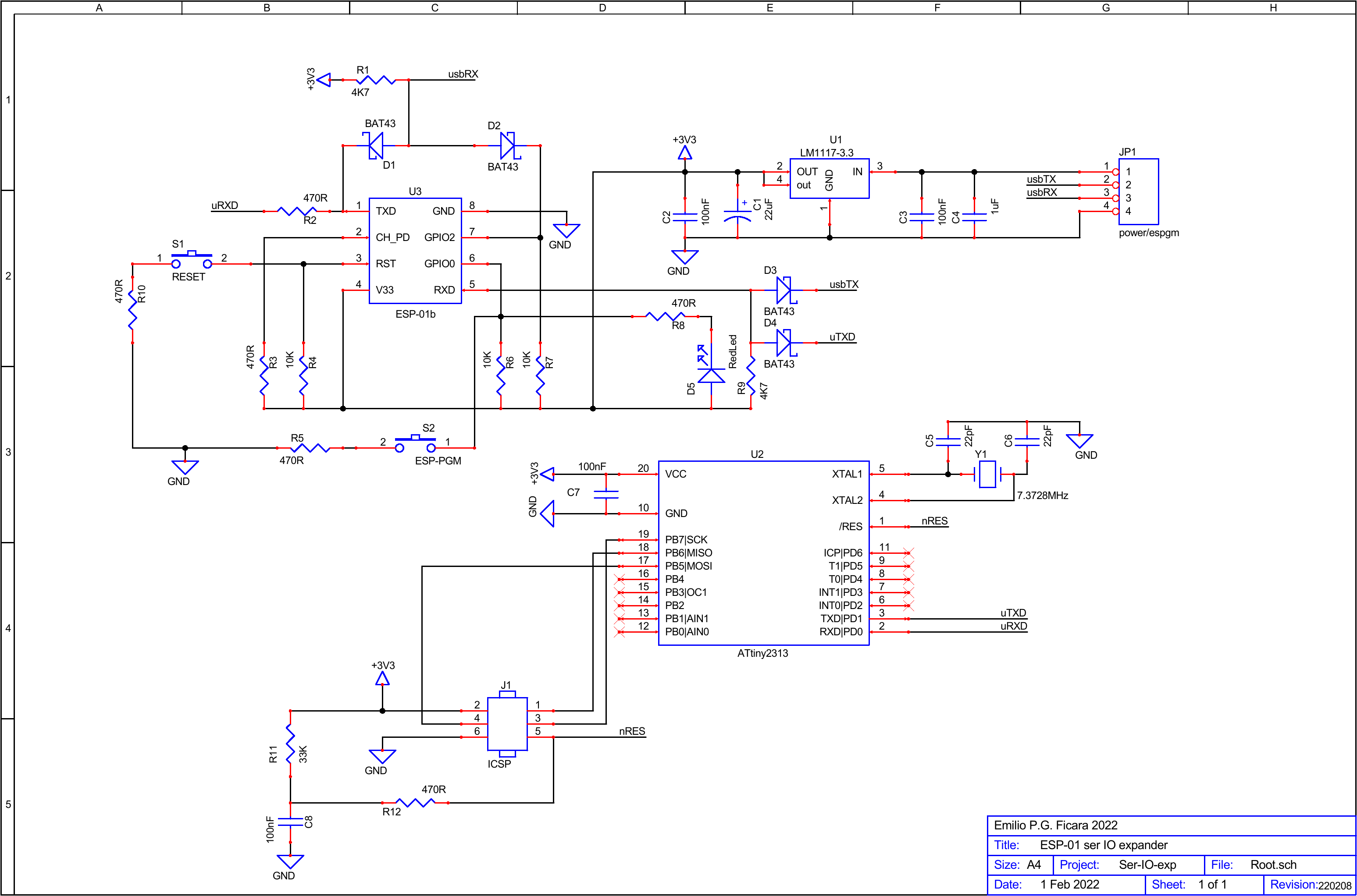
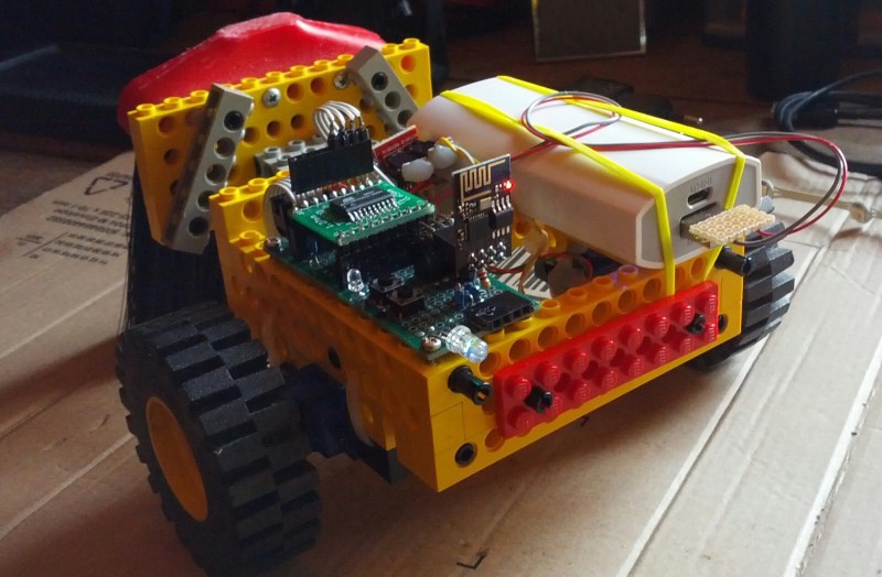
The photo shows the prototype and the removable USB-Serial interface that is used both to program the ESP-01 and as a debug serial monitor. The circuit is powered at 5V and has a 3.3V regulator for the microcontroller and ESP-01. Here is the complete schematic (note that the RGB LED visible on the prototype is not on the schematic, but is part of the "demo" you will find on the ESP-01 application for Arduino):
If you want more detail, you can download the pdf from the “files” section.
A brief note on the USB-Serial interface used in this little design. It is based on the PL2303 and has only 4 pins. I made a small modification as seen in the picture:
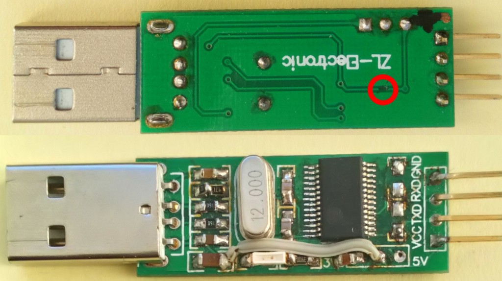
There is a track cut (red circle, top) and a wire jumper, plus a small cond. 100nF (bottom). This is to make sure that on the VCC pin there is 5V coming from the USB and instead the TXD and RXD signals are 3.3V. With other interfaces it is possible to do the same thing without cutting or soldering. Note that the circuit is assembled "by hand," because I had chips and PCB available from an old online purchase.
As you can immediately see on the schematics, there is a microcontroller type ATtiny2313 which is our I/O chip. To the question, "why that one?" I answer, "because I have a lot left over from an old project". Obviously, to perform this task, the micro must be properly programmed. I developed the firmware in C with the IAR's KickStarter for AVR, which can be downloaded (after free registration) from the manufacturer's site. The free, unlimited time version allows you to develop projects up to the 4K limit, which is absolutely no problem since the micro has only 2K flash!
In the “files” section you will find the complete project folder, with the source file in C and also with the hex file for those who want to program the flash directly without making changes.
Adding commands to the current ones is easy, just copy-paste one of the current ones and modify letters and operations to do appropriately, then recompile and reprogram the micro with the new version. The current commands are bare bones, but enough to do anything. Little work on the micro means that more will have to be done on the ESP-01 side, but this has enormously more resources, so logic tells us: get the resources where they are!
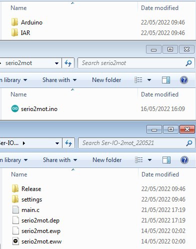
Here are the contents of the working folder:
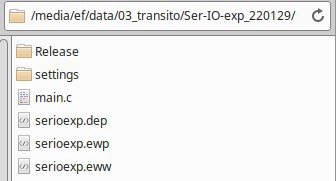
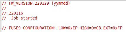
The serioexp.eww file is the one that, with a double click, starts the IAR development environment (if it has been installed!). The main.c file is the source in C, in a minimalist version, which you can expand as you like. The Release/Exe folder contains the serioexp.hex file that can be used to program the flash memory of the ATtiny2313 micro. If you do not want to make any modifications, this is all you need. In addition to the flash, you need to program the "fuses." This is the map:
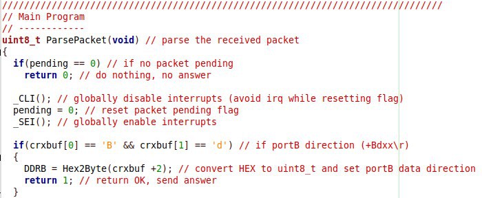
For those who do not want to download the file but just want to take a look, here is an extract from the command parser:
Everything was written keeping in mind that it will need to be easily expandable, although already this "basic" version contains everything needed to use the micro as a serial port-controlled I/O expander. This is a list of the commands currently implemented:
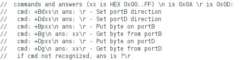
As can be seen, it is possible to set the direction of PortB and PortD (see diagram) and to write or read a byte to/from either port. Bit-level operations can easily be handled by the application on ESP-01 by holding an image of the port contents in memory and operating with OR and AND on that image before giving the command via serial.
Let us now look at a simple demo for ESP-01. You will find the application in the zipped file seriodemo1.ino.zip in the “files” section.
This simple demo turns on three leds (Red, Green, Blue) in sequence, then pauses briefly and starts again. The LEDs (the famous RGB LED in the prototype image) are connected to pins PB7, PB6, and PB5, which are also used on the ICSP connector for programming the micro. I then made a small flat cable that allows me to connect the LEDs or the programming connector as needed. The LEDs are of course connected via resistors. The red with 220R, the green with 1K5 and the blue with 1K. These values are experimental, fitting the led I used, but may not be suitable for others. Unfortunately, I do not have the characteristics of the led used. I bought it online from the usual "unreliable" sellers who tell you it is a common anode and then you find out it is a common cathode and the PDF is impossible to find, not knowing the actual type of led. Stuff happens...
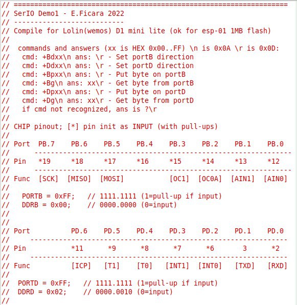
The first few lines of the .ino file contain some useful comments for understanding the connection between hardware and firmware. Here they are below, for those who want to get an idea before downloading it:
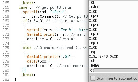
Instead, here is the output of the program in operation. Thanks to the special hardware that can mix the main serial output (TXD) to the secondary serial output (GPIO2) we can really see everything that is going on (left is the edit window, right is the serial monitor):
In many of my projects there is a "service pin" whose use is as a monitor of proper operation and activation of service procedures. In this case, the service procedure does not exist (there is only the start point) and the use is only to have a flashing LED indicating that the program is running smoothly. This is a perfect use for the GPIO0 pin, which is also used to send the ESP-01 module into programming. As a reminder, once the serial USB interface is connected, to send the module into flash programming mode you must press and hold the button on GPIO0, then press the button on the /Rst pin , then release /Rst and finally release GPIO0. This resets the ESP-01 and enters programming mode. With the circuit presented here, the "service" LED will be faintly on in this condition, while in normal use it will be flashing.
Note: All zipped files available for download are encrypted with the password: eficara.
Part 2 – Adding control for 2 motors (PWM)
I relocated in these days and my mobile lab is really minimal, but the passion is always there. I have made additions to the I/O expander to easily control two motors (direction and speed). Here is the practical application:
As in the previous case, the firmware is divided into two sections: the part on Arduino for the ESP-01 WiFi module and the part for the ATtiny2313 micro with the IAR's IDE (Kickstart).
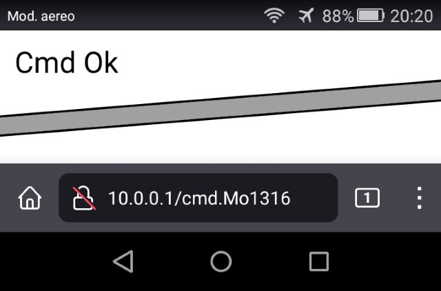
For Arduino, I wrote a minimalist test application, but with the advantage of being able to use any device with a web browser to send commands. Basically, the program as soon as it is turned on acts as an Access Point and runs a minimalist web server that parses the request and turns it into a serial command to the micro, receives the response from it, and sends it back as an html page to the device that made the request.
The AP SSID is "serio2mot" and the server responds to IP 10.0.0.1. Each command is like a web page whose name begins with "cmd." (this part is fixed) and is followed by the actual command. Be careful, the browser, in general, tends to add the prefix https (secure protocol) that we don’t need. For example, if in the address box we type: 10.0.0.1/cmd.Bg (command to read port B) we will see that this is transformed into: https://10.0.0.1/cmd.Bg and therefore we will not receive a response. It will then be necessary to make a small addition and write: 10.0.0.1:80/cmd.Bg which will force the browser to use a "normal" http connection on port 80. I recommend saving the commands as bookmarks, to simplify later submissions.
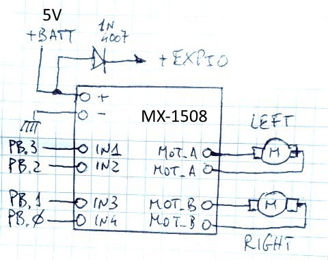
The firmware for the ATtiny2313 micro is an expansion of the previous version. I used a timer programmed to generate an interrupt every 5 mS, and in that function is the control of the motors with pwm. Since the motor power driver has two control lines for each motor, PWM is sent to one or the other line depending on the direction of rotation. To control two motors we therefore need 4 I/O lines, which I have assigned arbitrarily to ports PB.3-PB.2 (left) and PB.1-PB.0 (right). Note that, for compatibility with the previous version, this interrupt does not act unless a "Mo" command has been received. In fact, this command forces pins PB.3 to PB.0 as output and enables the motor/PWM function. Once enabled, this remains in operation until there is a "Hr" (hardware reset) command.

On the left: speed 1 (yellow) speed 6 (green)
On the right: speed 3 (yellow) speed 6 (green) – trigger point at center
As a power driver for the motors, I used an MX-1508 module
purchased online. This is the wiring diagram (refer to the general
diagram in the first part of this article). As a power supply I used
a power-pack for charging phones, which provides 5V on a USB port and
is rechargeable...
The commands available are the same as in the previous version with two additions (note: commands given via the web do not need the "+", it is automatically added by the firmware; for example, the web command "cmd.Bg" is transmitted over serial as "+Bg\n"). The new commands are "Hr" (hardware reset) which causes the Attiny2313 micro to be reset from watchdog and "Modsds" which activates the two motors. Let's see the latter in detail: 'Mo' is the actual command (Motor operate) and 'dsds' are direction and speed for the left and right motor, respectively. Direction can have the values '0' and '1' which are forward or reverse (then, it depends on the motor wiring!) while Speed can range from '0' to '7'. The firmware does not made validity checks on this data, it just does an 'and' between the received ascii character and a mask (1 in the first case, 7 in the second). If speed is 0, the motor is off; if it is 7, the motor runs at full speed, without PWM. Values from 1 to 6 instead cause the pwm to be proportional to the value. From my tests, this speed setting is sufficient for many applications.
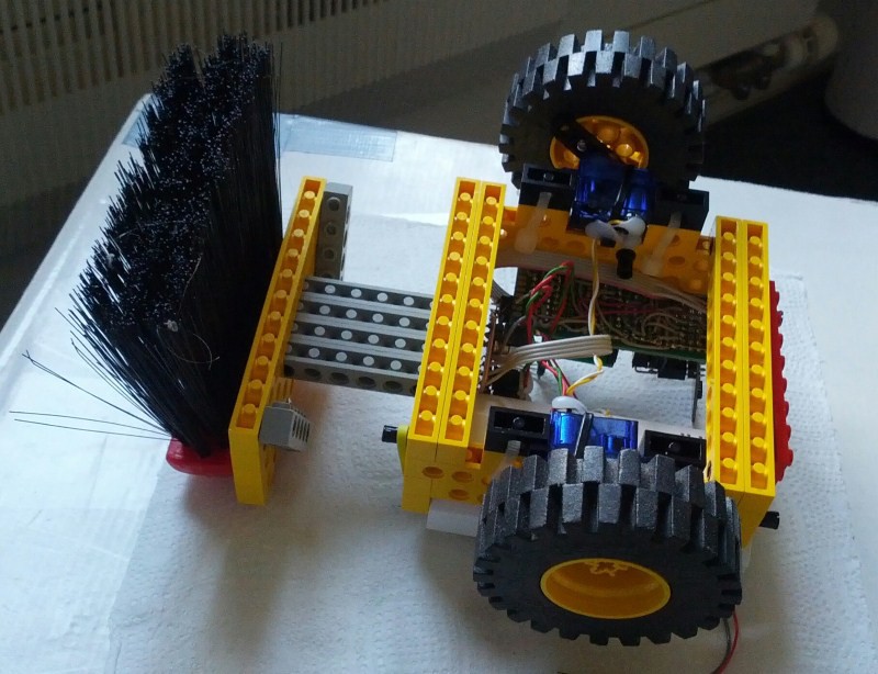
The device under test :)
Finally, we come to the firmware. In the “files” section there is a zipped file (password: eficara) named serio2mot_220522.zip where you will find the working directories for both Arduino and for IAR:
In the Release folder (of IAR) is the .hex file for those who want to program the ATtiny2313 micro without modification. The "fuses" configuration can be found at the top of the main.c file, and the .eww file launches the IAR development environment (if installed!). I hope this little project will be useful to others who, like me, like to build things. If you like my work and made modifications, please add a reference to my page, thanks!