 AIRPOCKET
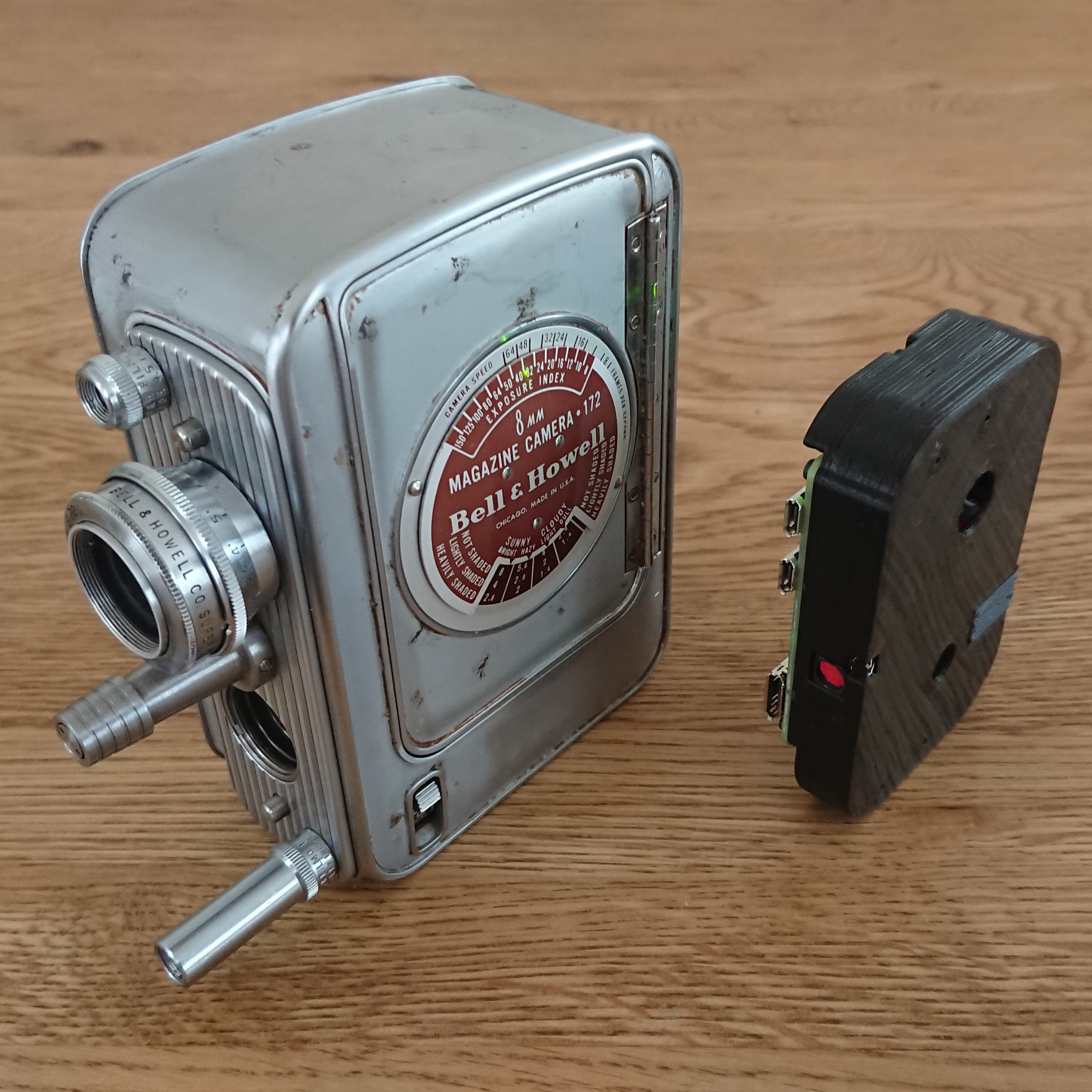
In my last project, I created a device that allows digital photography with a 70-year-old spring-driven 8mm film camera.
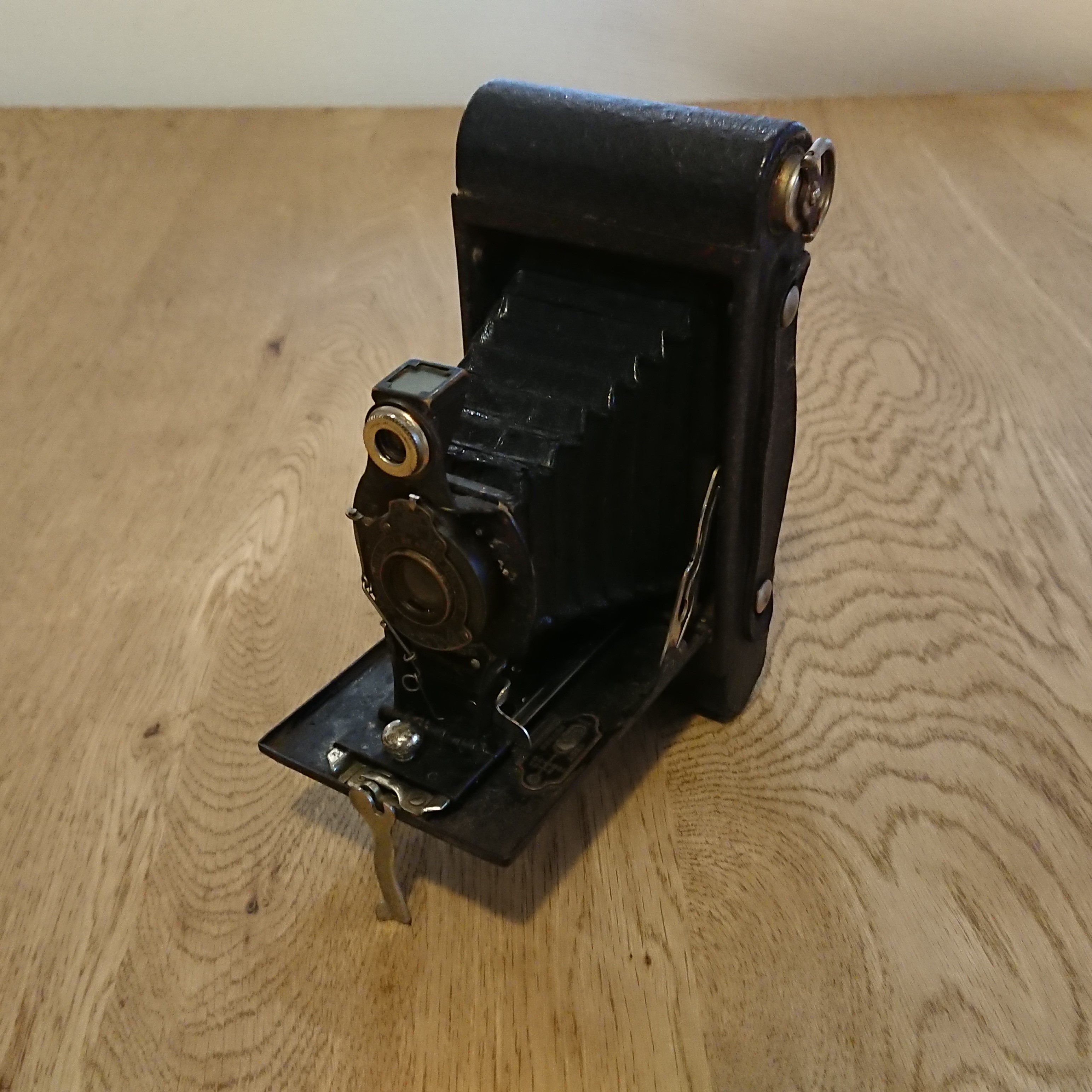
However, the number "70" is not a very crisp number. However, I wanted to describe it as "100 years ago," so for this project I digitized a camera that was made 100 years ago.
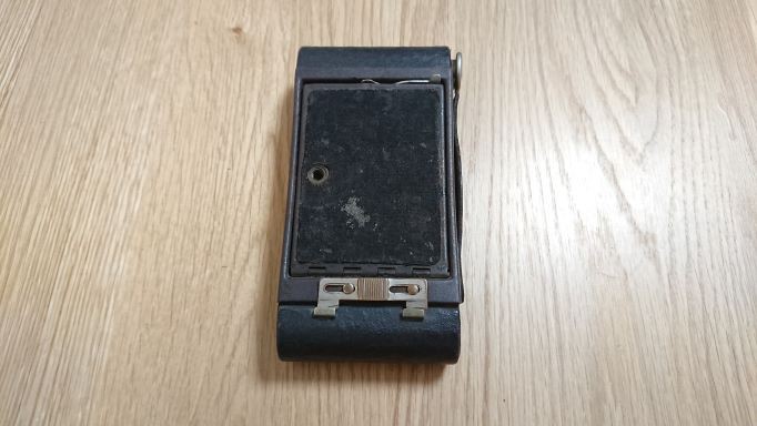
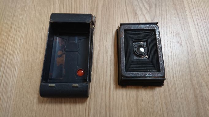
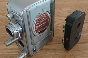
The camera I used this time is called "Kodak No. 2 Autographic Brownie". The bellows mechanism is very attractive and is 100 years old.
In the modern age, taking pictures with film has become very costly in terms of time, money, and technical acquisition.
In this project, we converted a 100-year-old camera, a valuable cultural heritage, into a digital camera while preserving the camera mechanism.
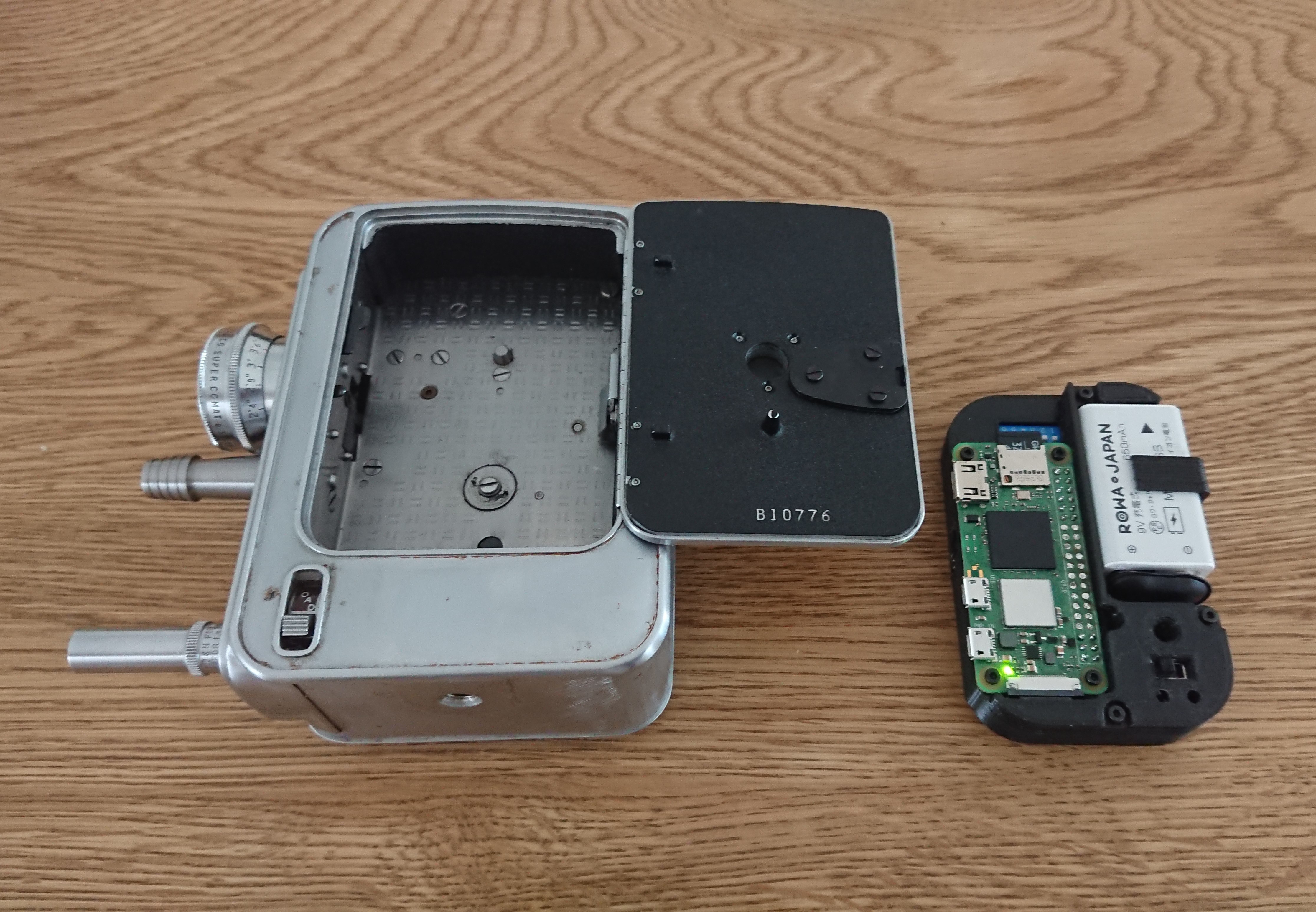
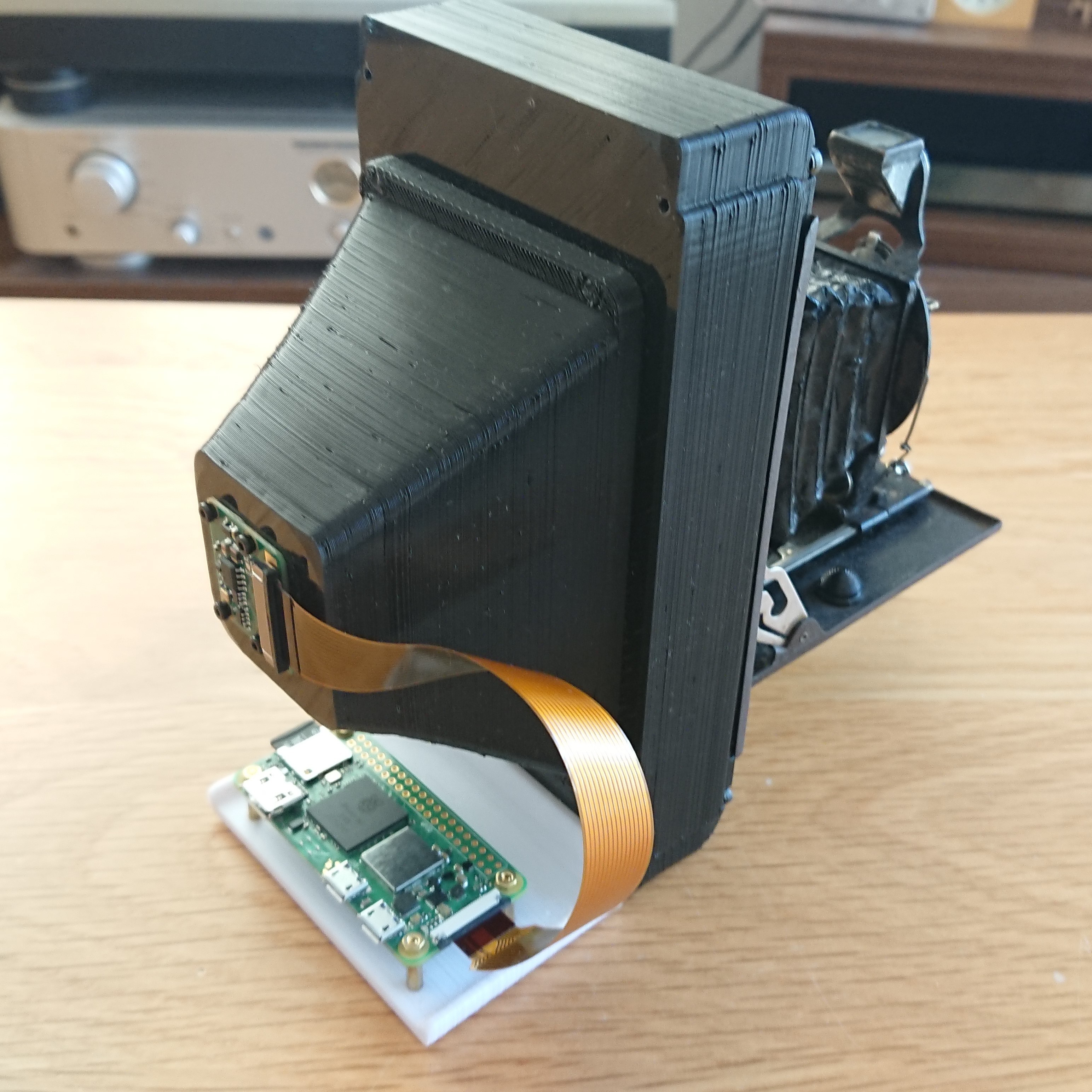
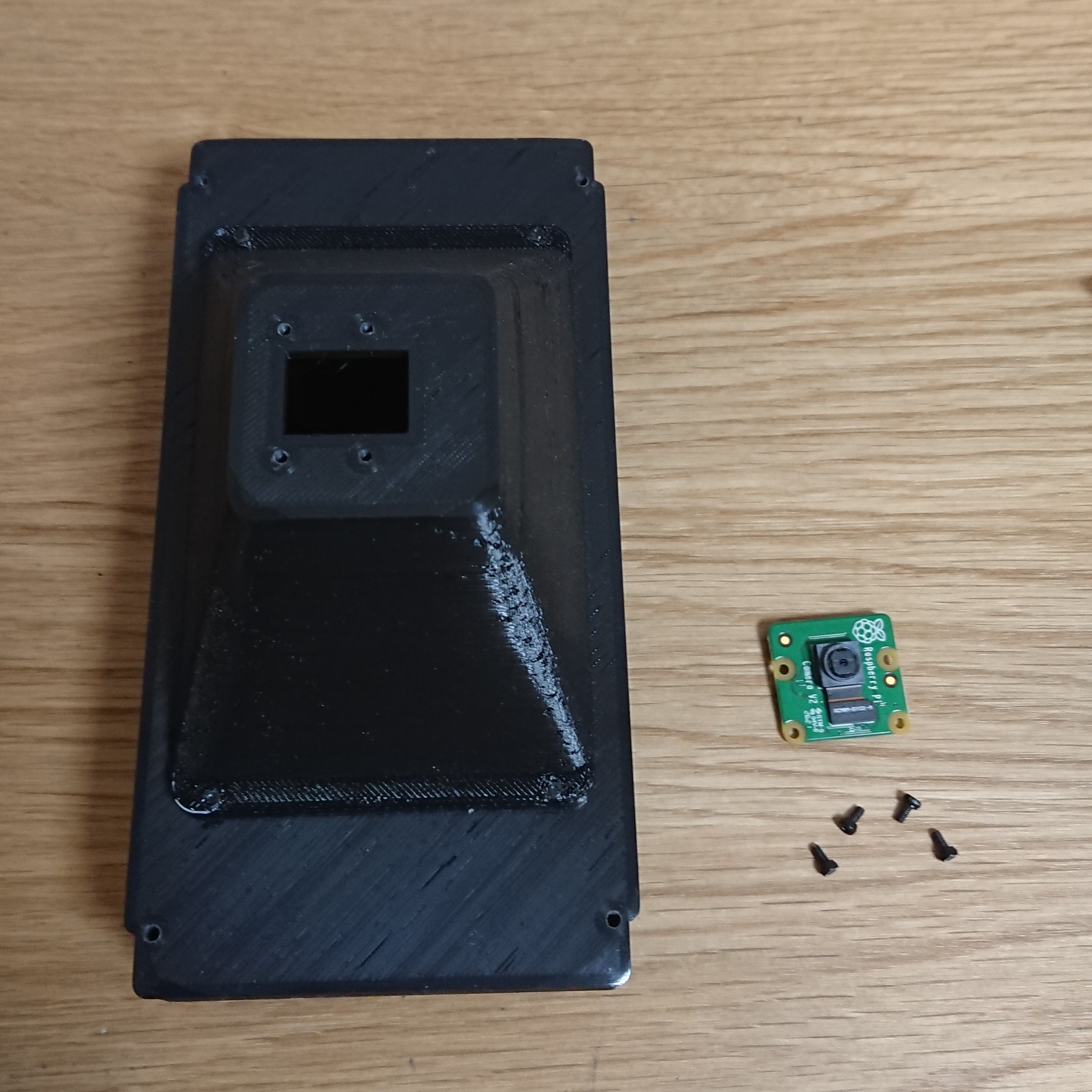
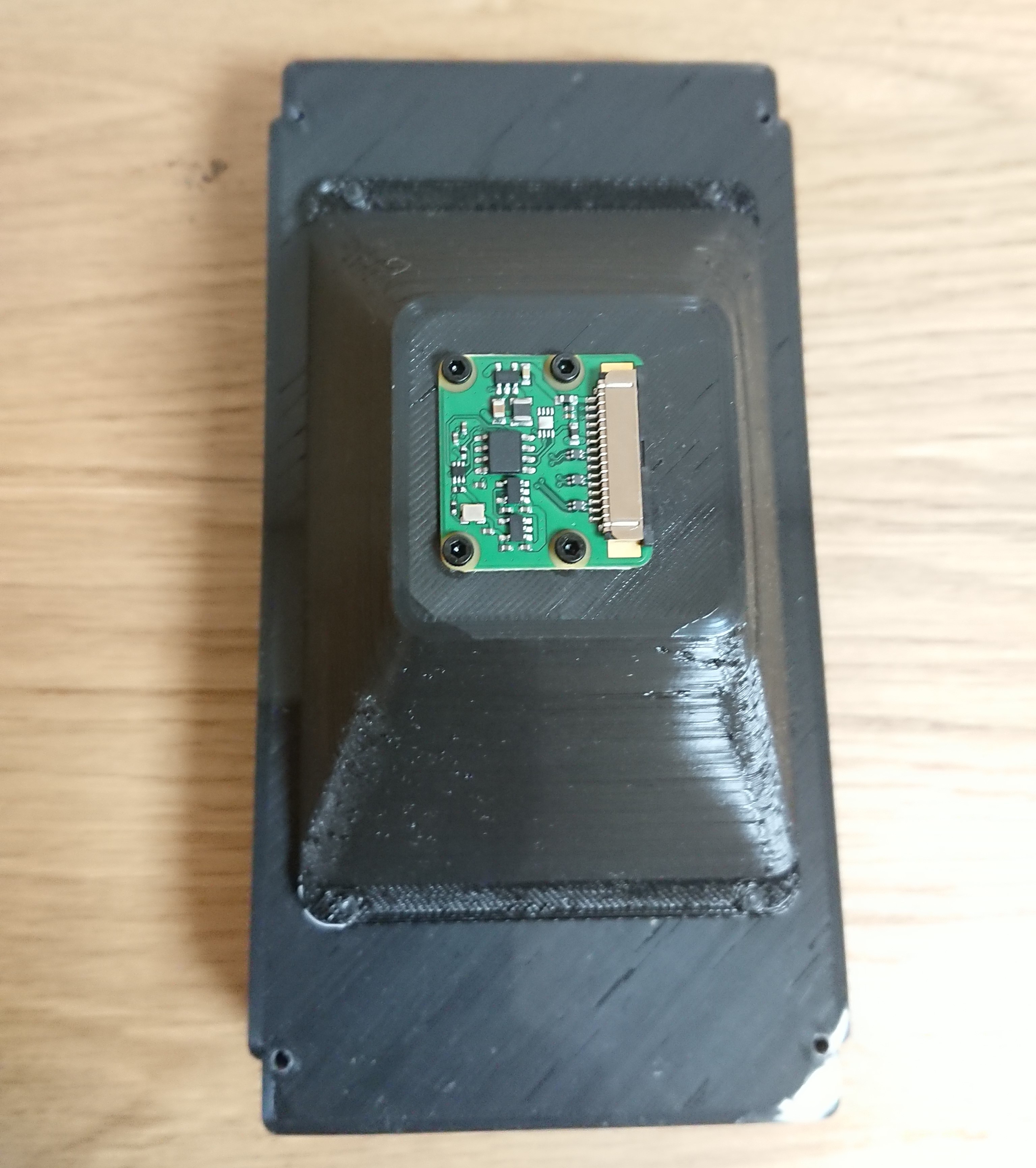
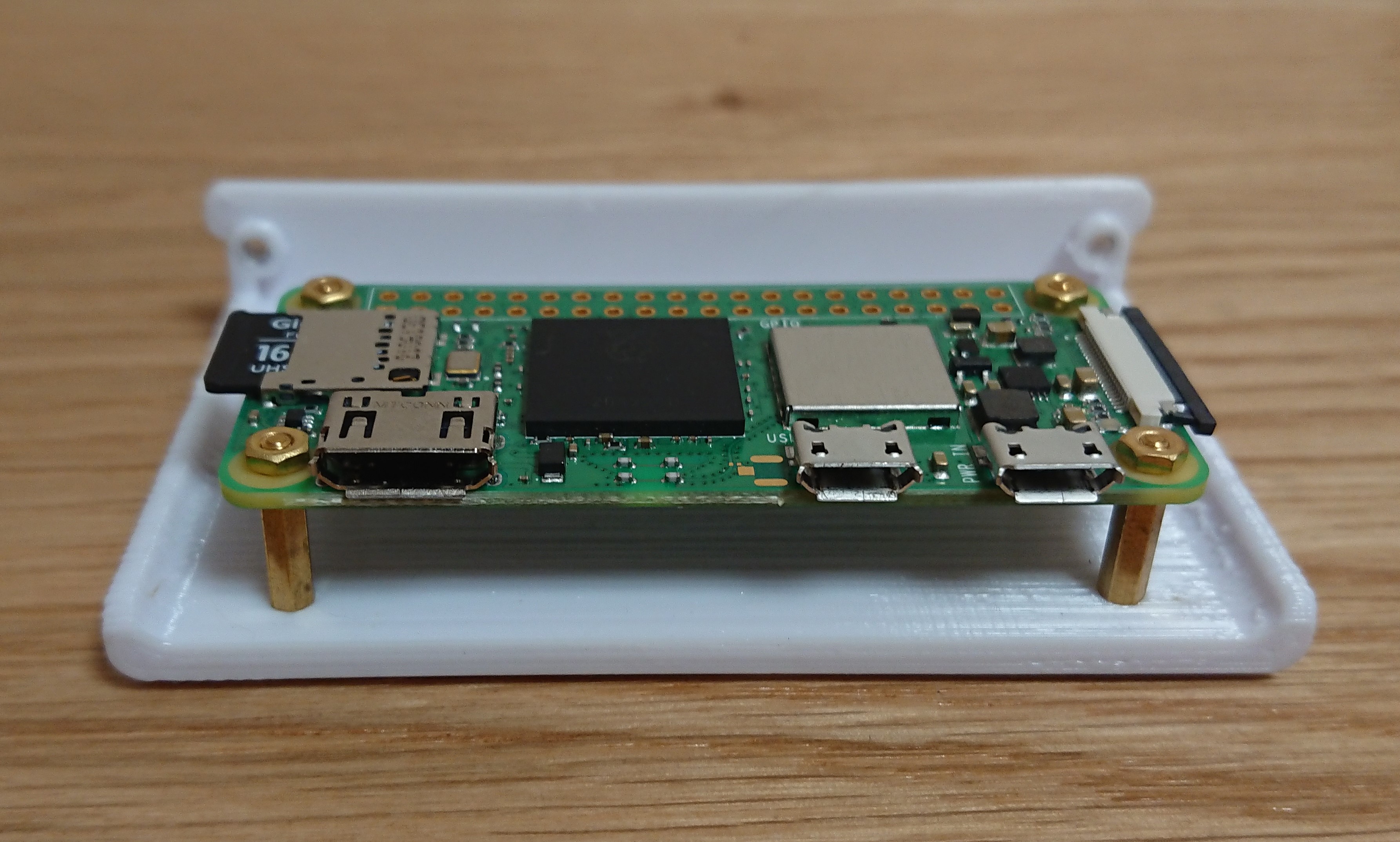
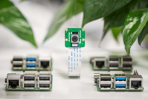
As in the previous project, I used a Raspberry Pi Zero 2W as the image sensor and a Raspberry Pi Camera V2 as the controller to enable the camera to capture video as well as still images.
One drawback of this system is that it tends to lack light. In addition to the original lens being very dark (f/8), much of the light is diffused when projected onto a screen, so there is not enough light for shooting in dark indoor locations. However, it can be used outdoors on a sunny day.
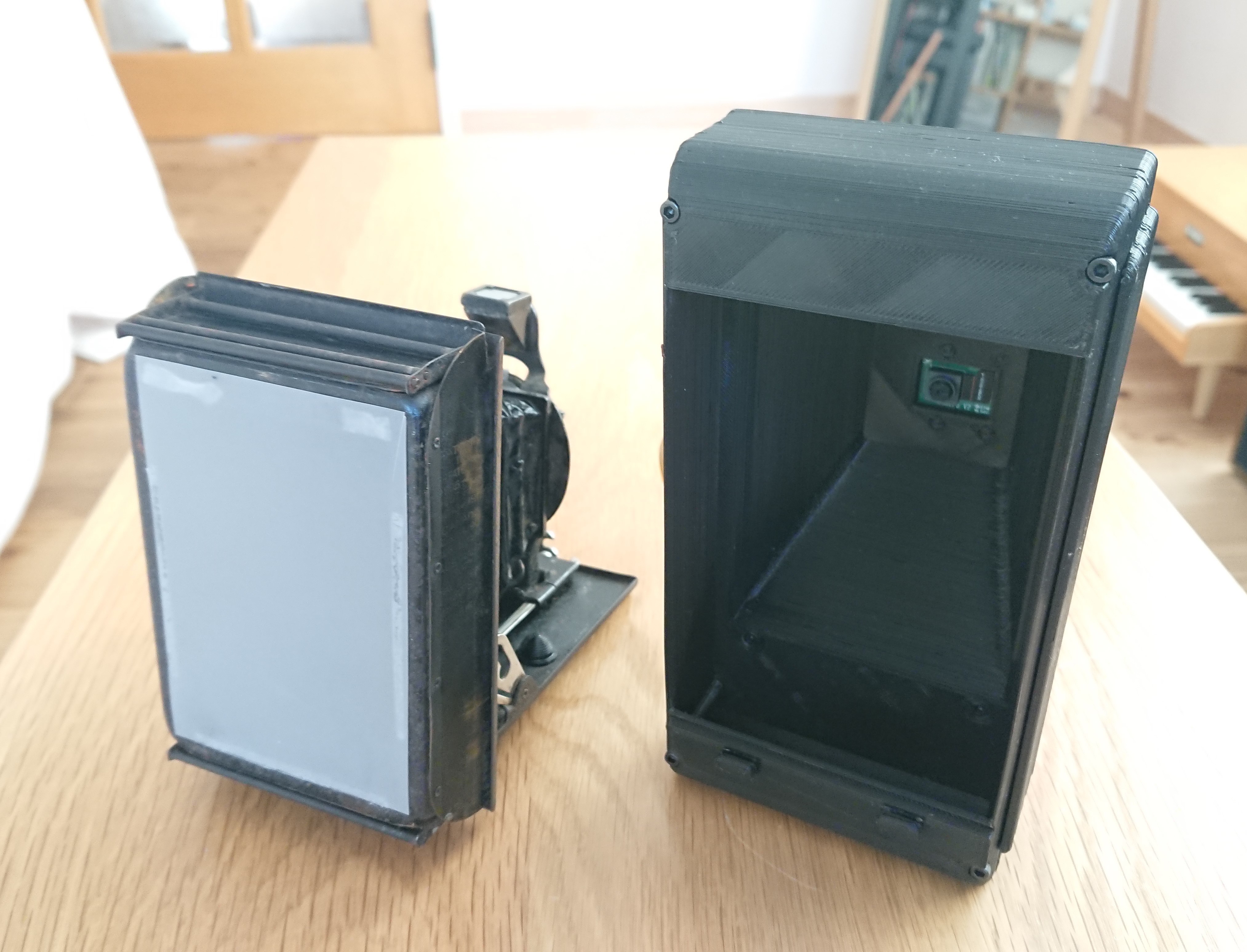
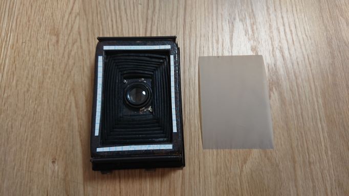
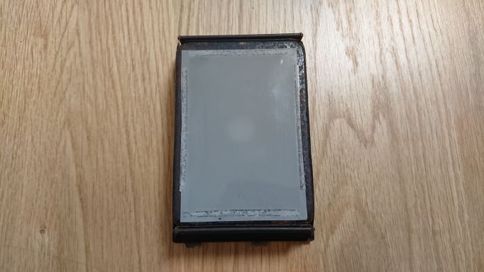
This camera can be split into the body, which also serves as the film case, and the lens section. When a screen for a transmissive projector is attached to the back of the split lens module, light rays passing through the lens form an image on the screen.
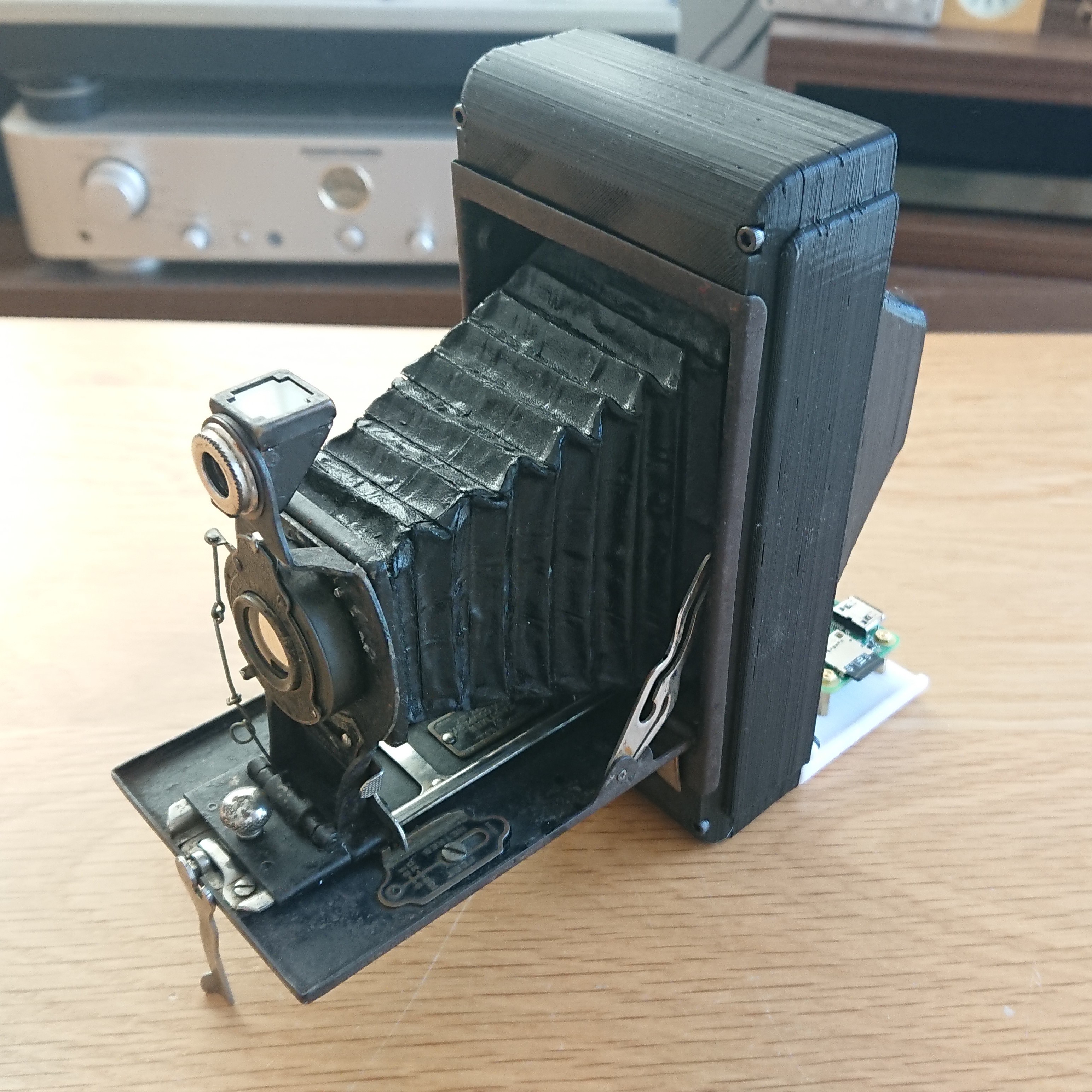
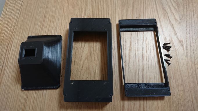
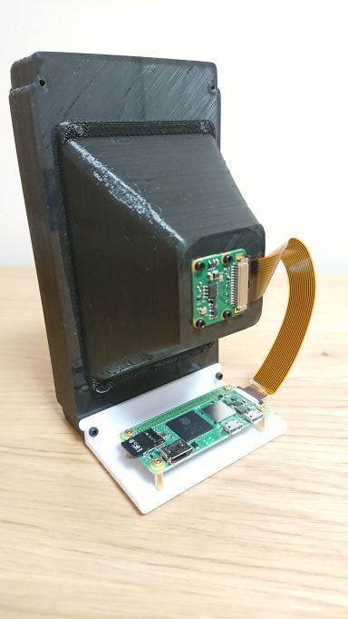
Since no film is used in this project, the original body is not used. Instead, a dark box will be installed to capture the screen with the Raspbery Pi camera. The dark box was designed to match the focal length and FoV of the Raspberry Pi Camera and printed out using a 3D printer.
Due to the lack of light, the image cannot be synchronized with the shutter speed. The shutter is left open and the Raspberry Pi Camera takes the image.
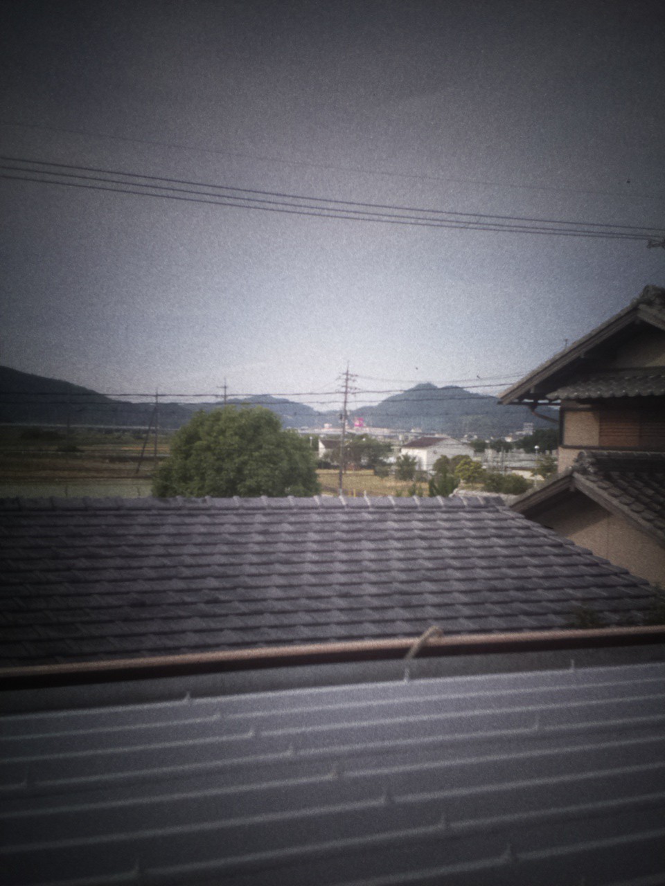
With this camera, I was able to take pictures like this one. The dark surroundings are due to vignetting and screen projection. Although it can be corrected to some extent on the digital data, it is left as a good feature of this camera.
 Arducam
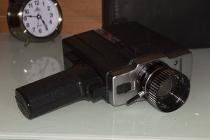
 Xabi Z
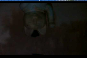
 tomburtonwood