 Emilio P.G. Ficara
Stepper motor tester and BLE Android App
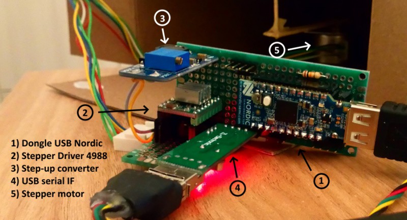
Here is another application of Nordic's USB dongle with the nRF52840 SoC. In this case, the module is used, together with a suitable control circuit, to control a stepper motor. All information on how to program the module with this application can be found in this article.
Hardware
Let's see the wiring diagram right now:
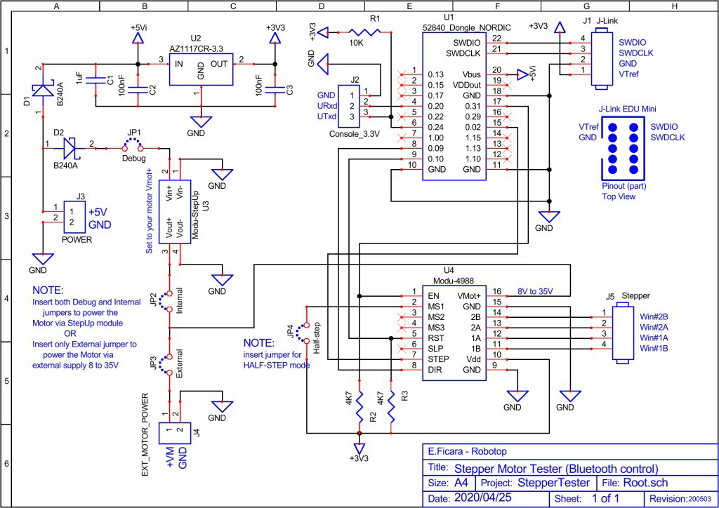
For a more detailed and clear view, you can download the original steptest-sch.pdf from “files” section.
The main component is, of course, the module with the SoC (System on Chip) nRF52840 from Nordic. However, having to drive a stepper motor, I added another module that acts as a power driver and I found one ready, based on the Allegro 4988 chip. This driver allows you to have different options on the motor driving, but I only used the JP4 jumper for the choice, limiting the driving to Full step (without jumper) or Half step (with jumper) modes. Another feature of this driver is that the voltage for the motor ranges from a minimum of 8 to a maximum of 35Volt. For my tests, I use small motors that run well between 9 and 12Volt and then I added a step-up DC voltage converter to use only one supply (5Volt) for the whole circuit.
On the diagram we also find the connector for the bipolar motor (4 wires). If we have a unipolar motor (3 wires per winding, with central socket) we can still use only the two external wires, ignoring the central one (valid for both windings).
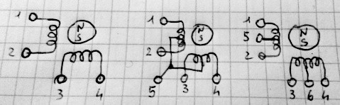
With the driver used in this circuit, only wires 1,2,3 and 4 are used. If in doubt, to determine which are, measure the resistances between the various wires with a tester.
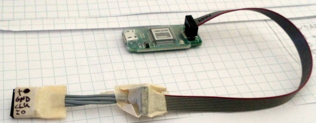
Then we have a connector for J-Link interface and for a serial console (via USB-serial converter at 3.3Volt). To program the module, the J-Link interface is not needed, you can insert the firmware through the USB connector of the dongle itself, as explained in this article. If you still want to use the J-Link interface, I recommend the J-Link EDU Mini model by Segger. I have also experimented with some "clones", but the original costs only a few dollars more and has all the drivers guaranteed and debugging support working 100%. The only critical thing is the small output connector, which forces you to make a "home made" adapter to go to the classic 0.1″ step used in prototype boards. I did it like this:
On the hardware side, since all commercial modules are used, there is nothing special to say. For the step-up DC converter, I recommend calibrating it for the desired voltage (there is a trimmer on board) before connecting it to the circuit. Obviously, the external 5 Volt power supply must be able to "withstand" the load of the circuit and the motor. The step-up DC converter I used is declared to have an efficiency greater than 77% and a maximum current of 1A, so it's fine for small motors. I used for the tests a 5V-1.5A power supply and a ULM-15 stepper motor with 24 (full) steps per revolution. The step-up DC converter is rated for 10V output. I also selected Half-Step mode with the JP4 jumper, so 48 clocks are needed for one full revolution.
In the video that follows, here is the circuit in operation. To make things more fun, I put a small magnet on the motor shaft and closed everything in a box; then, I took a paper clip and glued it on a piece of paper on which I drew a toy car and so, when the engine is running, the paper clip is pulled by the magnet and it looks like a car on the track!
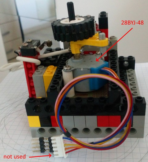
Below is an old mechanical prototype, built with Lego, in which a model 28BYJ-48 geared-down stepper is used. You see 5 wires on the connector, but as we said, only 4 wires are used. Note that the circuit presented in this article is NOT appropriate for stepper motors running at 5 Volts. The 4988 driver, in fact, works with a Vmot from 8 to 35Volt and below 8Volt it is not reliable or does not work at all. For very low voltage stepper motors (3 or 5Volt), I suggest using the usual ULN2003 (in case of motors with 5 or 6 wires) or something like the Sanyo LB1909M (obsolete) or its descendants for motors with only 4 wires. Unfortunately, both with the first and with the second of these drivers, we have a completely different functioning from that of the Allegro 4988 (or the functionally equivalent LM297 - LM298). The driving is NOT carried out by means of the RST, EN, DIR, CLK signals, but by switching the individual motor windings on and off with a specific sequence. A driver with the same operating mode of the 4988, but with a working voltage from 2.5 to 10.8Volt is the DRV8834 from TI. Also for this, there is a ready-made module with the pinout at 0.1″ step. For now, let's go ahead with this firmware version and the 4988 driver; it may be that I have to develop also a version with direct motor driving, to use my micro motors recovered from various devices.
Firmware
I developed the firmware for the nRF52840 micro on the Linux Foundation's free RTOS Zephyr platform. The program is quite simple: there is an initial procedure in which all the peripherals are initialized and two threads are launched, one for the serial console and the other for the bluetooth management. Both the serial console and the bluetooth are used to give commands and receive responses. Since both work at the same time, it is possible to manage the stepper motor both via a serial terminal with USB-TTL interface at 3.3V (protocol 115200, N, 8.1) and via bluetooth (we will see the App for Android later) . To understand what can be done, let's see the screenshot of my PC used as a terminal. Note: the miterm program, written by me in FreeBasic, is available in the download package attached to the article.
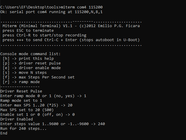
Here is the complete list of commands that can be sent via the console. Some are single-key (a letter is already the command) while others need a parameter. Let's see the list:
h - immediate command: prints the help with the list of commands
p - immediate command: sends a reset impulse to the driver
e - Enable command, parameter and CR follow; if 1 disables, if 0 it enables the driver
s - Steps command, parameter and CR follows; the steps range from -9600 to -1 (counterclockwise) or from 1 to 9600 (clockwise)
f - Max frequency command, parameter and CR follows; values range from 1 to 20 (* 25), so value 1 is 25 SPS (Steps per Second) while 20 is 500 SPS
r -Ramp command, follows parameter and CR; currently it accepts only the values 0 (no ramp) and 1 (ramp active)
Speaking about the ramp, in this firmware release I made it in a non-linear way. With the ramp, the motor always starts from the minimum speed f1 (25 SPS) to reach the ramp at the set one, let's suppose f20 (500 SPS) and then slow down again to f1. For each frequency there is a proportional number of steps: there will be only one step with f1, two with f2, three with f3, up to 20 with f20. If the number of steps set for the movement is too low to be able to make a full ramp, the firmware automatically reduces the maximum frequency set.
Two LEDs are used on the USB dongle. The green one flashes on reset and then remains off until a movement of the motor is performed (command s). During the execution of the command, the LED turns on, and then turns off at the end. The second led is part of the RGB led on the module. Lights up blue for 250mS when a command from Bluetooth is received. Another important element is the small button. This serves as an “emergency button”, ie if you have given a wrong command that causes the motor to run until it collides with something, pressing the button will stop everything and the motor driver will be disabled. This is particularly useful because the movement command, once started, cannot be stopped.
Software
I have already created in the past a small application in VisualBasic to test stepper motors. This is the screenshot:
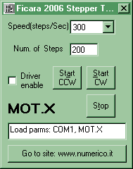
If you are interested there is this reference in my old CNC site section. I would like to point out that a few years have passed and the website "numerico.it" no longer exists, or if it exists, it is no longer mine!
Now I have written an Android app that does more or less the same things, but has the advantage of connecting to the firmware via Bluetooth BLE, which is handy because you don't need a PC next to you to give commands. Here is the App icon:

As usual, the icon is very minimalist! I wrote the software with Anywhere Software's B4A . I bought this software (great, believe me) in 2011, but today it's FREE and I highly recommend you to download it from the manufacturer's website and start using your smartphone creatively.
This is what the App looks like once installed. Warning: it's not on Google Play, but you can find the apk in the attached zip file. You must authorize installation from "unknown sources" on your smartphone, otherwise it will not be possible to run it.
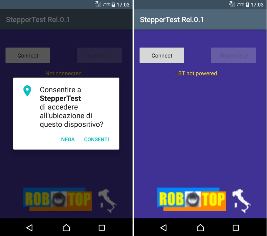
In the box on the left we see what happens as soon as the App is launched. If we have Android from version 6 onwards, we will be prompted to authorize access to the location. This has no apparent logic, but if you want Bluetooth BLE to work, you need to enable it (ask Google why, not me). In the box on the right we see what happens if we have authorized the location, but we have not turned on the Bluetooth! I remind you that you must also activate the location (I use the "GPS only" mode). Suppose we have done everything necessary ... We are now in this situation:
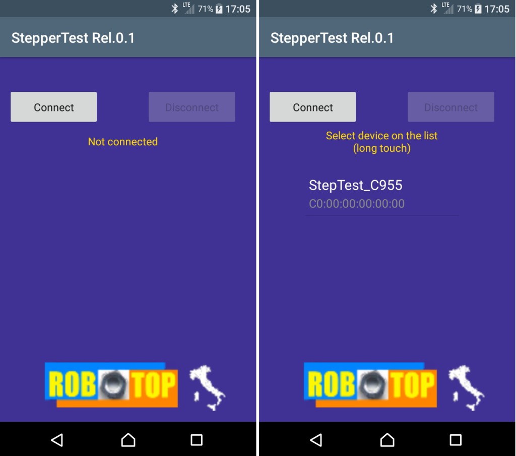
Click "connect" and the program will scan for "visible" Bluetooth devices nearby. If we find one called StepTest_xxxx, we're good to go. The xxxx field varies depending on the nRF52840 chip. These are the last two bytes (in HEX) of the device ID imposed by Nordic. It is not a unique number, but it is extremely rare that you will find two that are the same. In any case, we only need it in case we have multiple circuits and we want to decide which one to control. To select and connect, we long press on the item in the list (note: if you are in an office you will see a lot of devices, select the right one!)
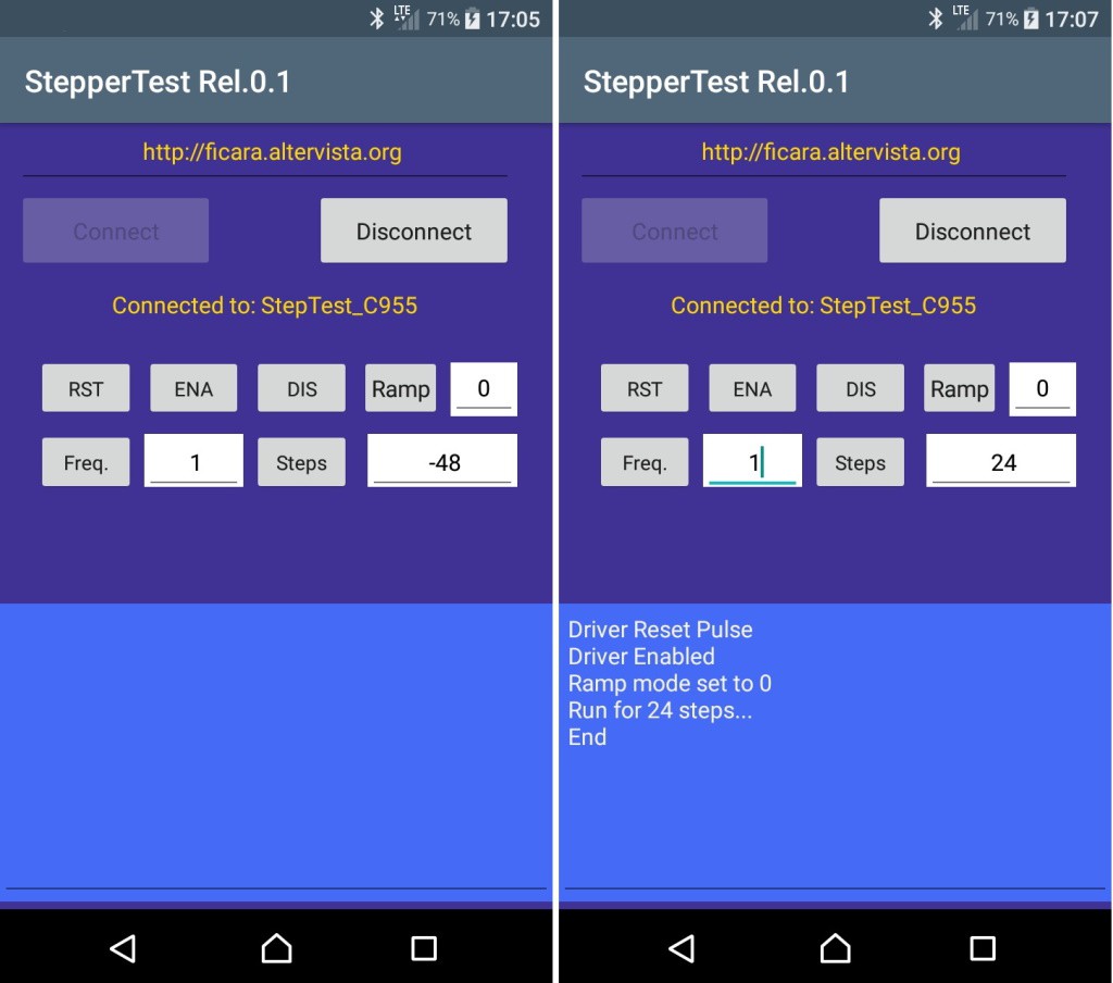
Here on the left is the command window, just initialized. For the commands, the same things apply as for the version via serial terminal. In fact, things run in parallel and it is possible to give commands both from the serial terminal and from Bluetooth (once connected). In the blue message window you will see the answers coming from the circuit and / or the errors in case of wrong data entry. To insert the data, for example the frequency, write the desired number in the edit box and then remember to press the button on the left, which causes the transmission of the data (if correct) to the circuit.
On the right we see an example of commands sent. The motor rotated for 24 steps at frequency 1 (25 SPS) and without ramp. By convention, positive steps mean clockwise and negative steps counterclockwise. If your circuit is working upside down, swap the wires of the motor windings.
Conclusions and annexes
That's all. In the attachment you will find, zipped, several files. Let's see them:
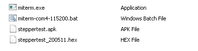
- miterm.exe is my small serial terminal, really basic, but it works and requires no installation.
- miterm-com4-115200.bat is a batch file that launches the application with the parameters Com4, 115200, N, 8,1 (you can edit the batch to change speed or Com port).
- steppertest.apk is the Android App we have seen
- steppertest_200511.hex is the file to be programmed in the Nordic USB dongle.
The zip file has a password that is: eficara. Before any unzip / exec operation on files downloaded from the Internet, is better to check the SHA-1 code to be sure that the file is intact and not manipulated by others. In this case the hash must be:
SHA-1: 57A57B4673FBCBCA0C972787D8C88BFACF4A878B
You can find the file steppertest_200511.zip in the “files” section.
I remind you that I take no responsibility for any problems that may arise with the download and / or installation of the material made available. It is material of a hobby nature and made available free of charge, so you, by using it, take full responsibility. I am not an expert on "legal terms", but I hope the concept is clear enough.