Arshmah Shahkar
Uses of Flame Sensor:
Flame Sensors can be used as safety equipment in detecting fire in different areas or things like:
- Automobile
- Fire Fighting Robots
- Garage Safety Equipment
- Warehouses
- Domestic use
- Hydrogen stations
- Industrial use
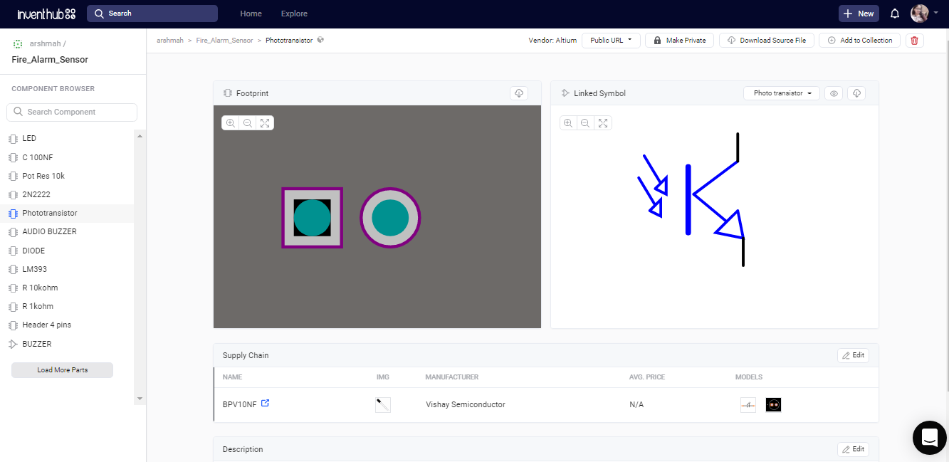
Photo Transistor:
A Phototransistor is similar to the transistor except that it has a light-sensitive Base terminal. It is an LED with three terminals i.e. emitter, collector, and base. It is an NPN transistor This phototransistor is coated with black epoxy, making it sensitive to Infrared radiation and this particular Photo Transistor is sensitive to Infrared Radiation in the wavelength range of 760nm to 1100nm. I have uploaded the symbol and footprint online on Inventhub. Those who want to implement my design, do not need to design their parts, instead, they can download my designed parts and can use them in their design.
Specifications:
- The wavelength range of fire detection is 760nm to 1100 nm
- Distance of detection is 20cm (4.8V) ~ 100cm (1V)
- The angle of detection is about 60 degrees
- Adjustable detection range
- Operating voltage 3.3V-5V
- Digital and Analog Output
- A Potentiometer to adjust the sensitivity of the sensor
Working:
This PCB board is divided into two parts;
- Flame sensor circuit
- Buzzer circuit
The flame sensor circuit consists of three pins; VCC, GND, and DO. Vcc and Gnd can be connected with +5V and Gnd respectively. DO is the digital output given the pin11 of the Arduino as a flame sensor pin to detect the fire.
The buzzer circuit contains an NPN transistor i.e. 2N2222, 1kohm resistor, a diode, and a 5V buzzer. It is connected to pin12 of the Arduino. It will become active in case of any fire or flame.
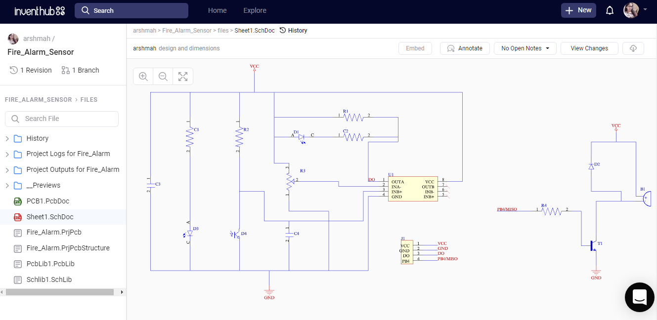
Schematic Diagram:
I have designed a schematic diagram in Altium Designer. I have created an empty project online on Inventhub and uploaded my schematic file there. Making project online is helpful for the users who want to implement my design. They can visually view and download it from the Inventhub easily and can directly implement the design without any error. I can also add multiple files like PCB files, BOM document file, and library files by clicking on the ‘Add file’ button.
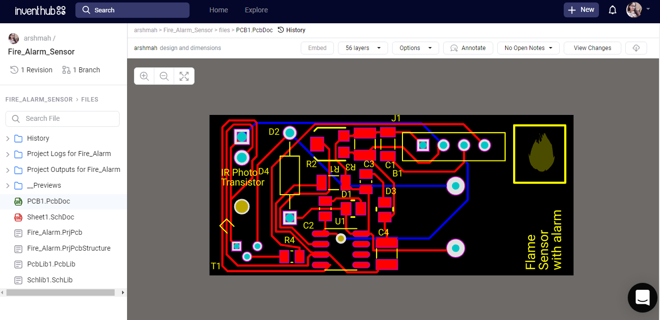
PCB Design:
For the fabrication, I have converted my schematic file to the PCB file. Here I can view my board in 3D, check for the errors, and edit the shape of the board. I have uploaded my PCB file on Inventhub. Instead of visiting the manufacturer, I can send him the PCB file, he can easily download it and can fabricate my board. This is also useful for the users who want to design my board, they can view and download it from the Inventhub.
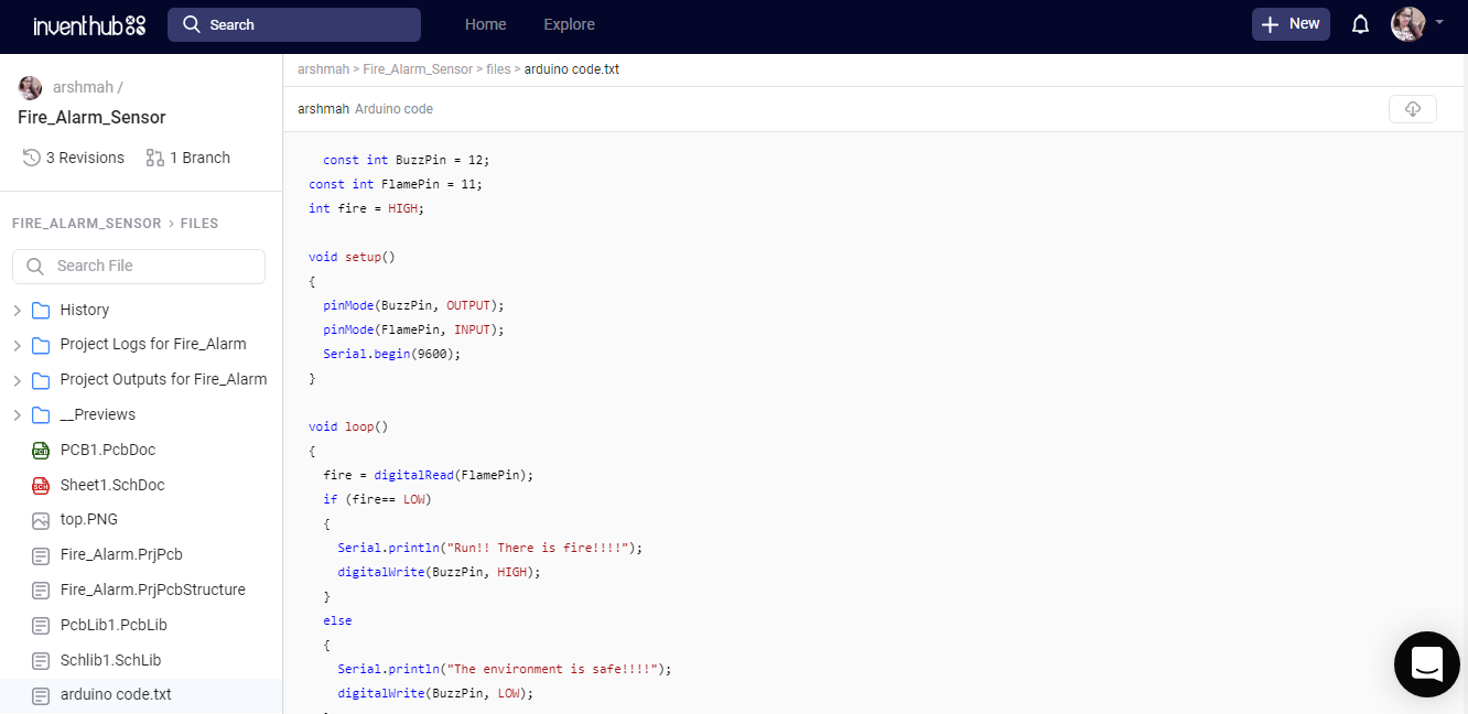
Arduino Code:
I have created a text file that contains the code for this flame sensor and uploaded it on Inventhub. In the code, I have declared two pins; pin12(PB4/MISO) of the Arduino for the buzzer and pin11(PB3/MOSI) of the Arduino for the detection of flame. Initially, the output from the flame sensor is high. When the sensor detects any fire, it becomes LOW. The Arduino detects this low signal and activates the buzzer.
In case of detection of fire, it will print a message on the serial monitor. But in case of no fire, it will remain calm and there will be a message of no fire appearing on the serial monitor.
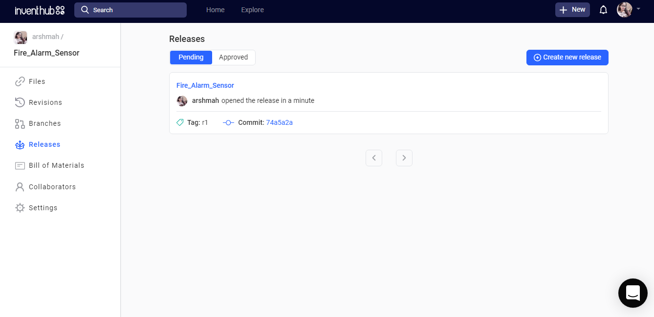
Release file:
To get my whole project in one place, I have created a release file of my project after uploading all my design files on Inventhub. This file contains my schematic, PCB, library, and all history files in a ZIP file format. The manufacturer, instead of viewing and downloading each file one by one, just needs to download this release file and he can easily fabricate my PCB without making any errors.
BOM file:
I have created a BOM file in Altium then I have uploaded it in CSV format on Inventhub where I can calculate the total cost of my design by selecting the ‘supply chain’ option. I can view the components and can read their datasheets also. I can select my distributor for the components depending...
Read more »
 Sagar 001

 Mike Kushnerik