 Ralph
RalphThis is a simple circuit, FETs switch on the different relays and an indicator LED. I've included some input supply filtering and an on board 5v regulator to allow a digital interface to be used if needed. To keep things simple, I use a rotary switch to select the active port.
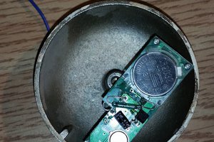
The circuit board includes smd components to handle all the switching.
Although this can be used as an antenna switch, I use it the other way round, to switch transceivers to one antenna. The port to port isolation is greater than 70dB, which is more than enough to ensure I don't damage a receiver input when transmitting on another one (I only operate up to 100W).
The board has a PowerPole input connector for 12Volts and uses a few transistors to switch on the relay and an indicator LED for each channel.
I know most folk like to use PL259 coax connectors, but I just don't like them, so opted for BNC instead. You could of course wire in PL259 sockets with short lengths of coax.
The main parts for the board are (with suggested Mouser part numbers):
- 1 x rotary switch (if used) : 611-A10403RNCQ
- 5 x BNC sockets : 712-CONBNC001
- 4 x relays : 470-4058560000
- 2 x PowerPole Connectors (if used) : 733-58257-1095
 Jared Young
 Annelle Rigsby
 Quinn
Quinn
 Milad
Milad