danjovic
Ultradian Rhythms
The conventional workday was designed to keep people busy during the whole working period, assuming that they can be productive the entire time, but as we all know that simply doesn't happen because our bodies are chemical engines that works in cycles (or rhythms) shorter than a day, but longer than an hour, known as Ultradian Rhythms. Such cycles are the reason why your brain and your body begin to crave for a rest period after about 80-90 minute of intensive work.
Source: https://organixx.com/ultradian-rhythm/
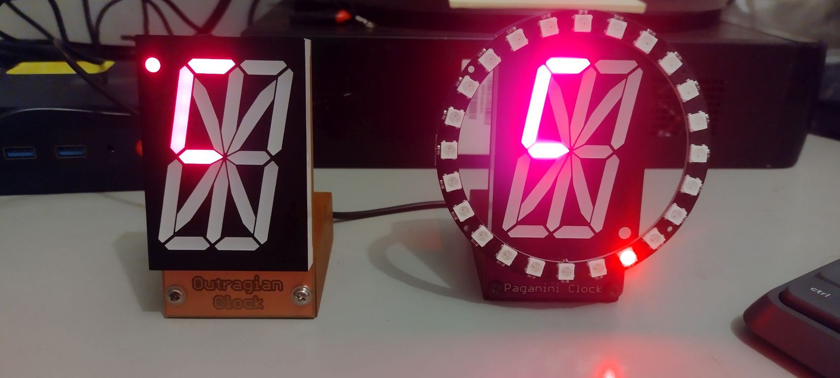
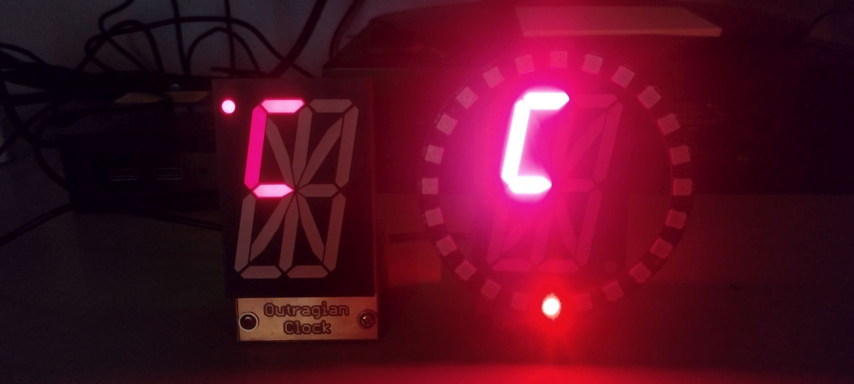
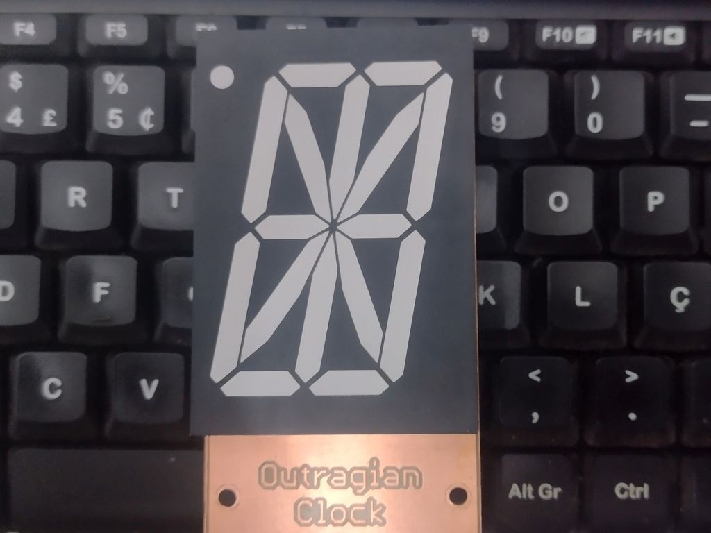
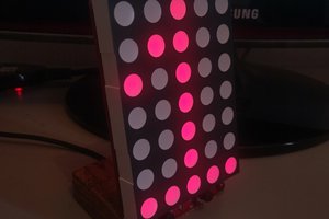
16 segments
The time is representation keeps some resemblance with traditional clocks, though it uses 8 major divisions, instead of 12.
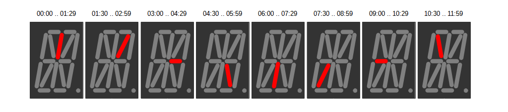
While the inner segments represent the 90 minute intervals, the outer segments represent a 10 minute subdivision. As the first state is no outer LED lit, we have 9 possible states. Perfect!
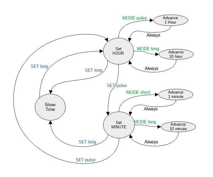
State Machine
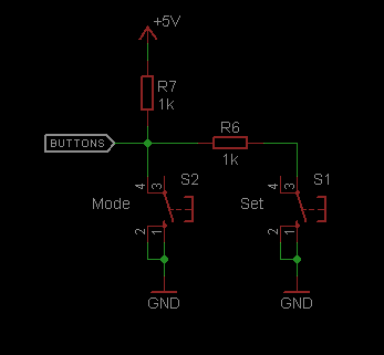
The main clock program runs a state machine every 10ms and provides two buttons to operate (MODE and SET) . The state flow is performed by two different events of the buttons: Short pulse and long press.
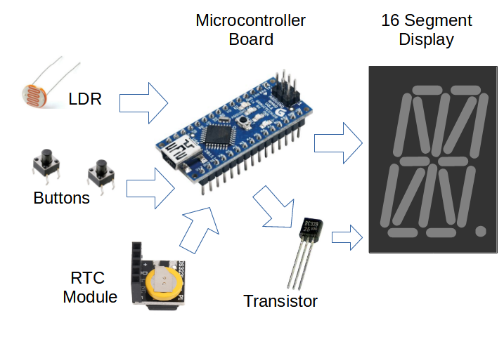
Block Diagram
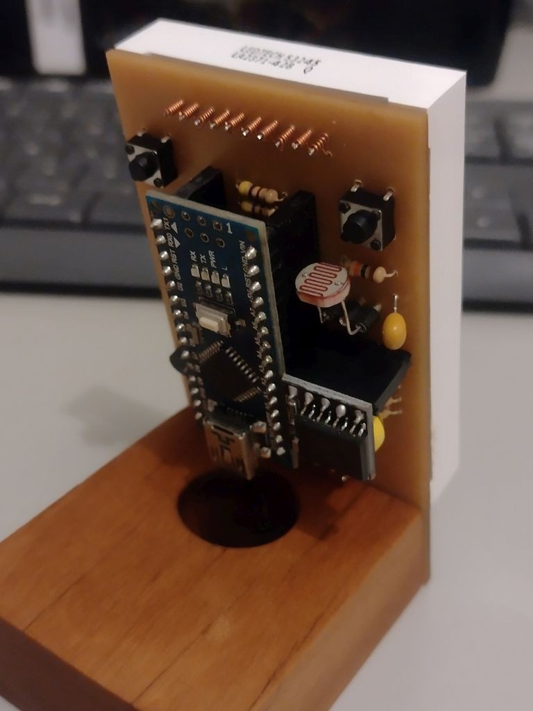
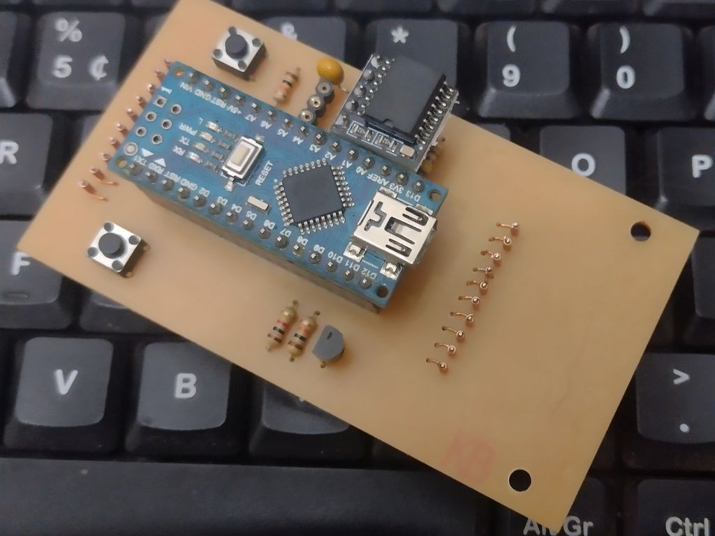
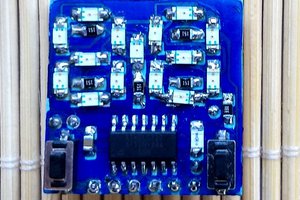
The circuit is built upon a micro-controller with enough pins to drive the 16 segment, an I2C RTC module and the buttons.
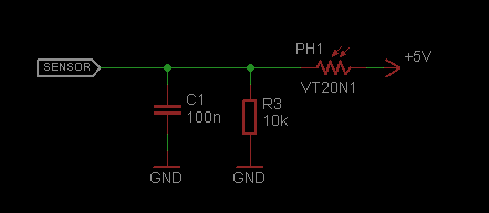
Additional resources are light sensing (LDR) and PWM control
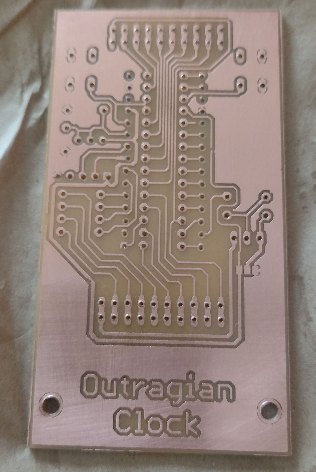
Circuit
The whole circuit is presented below. All of the pins of the microcontroller are used including the two "extra" ADC lines (A6 and A7) .
The buttons are read using one analog input. The expected ADC values are:
| State | ADC Reading |
|---|---|
| No button | ~ 1024 (close to max) |
| MODE button Press | ~0 (close to min) |
| SET button Press | ~512 (close to middle value) |
The LDR is also read by the ADC . The expected values are:
| Ambient Light | ADC Reading |
|---|---|
| Dark | ~0 (close to min) |
| Daylight | ~1024 (close to max) |
The Brightness of the display is controlled by one of the PWM outputs of the microcontroller that drives a PNP transistor which in turn chops the VCC of the Common Anode display.
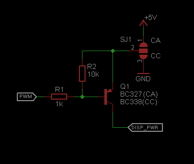
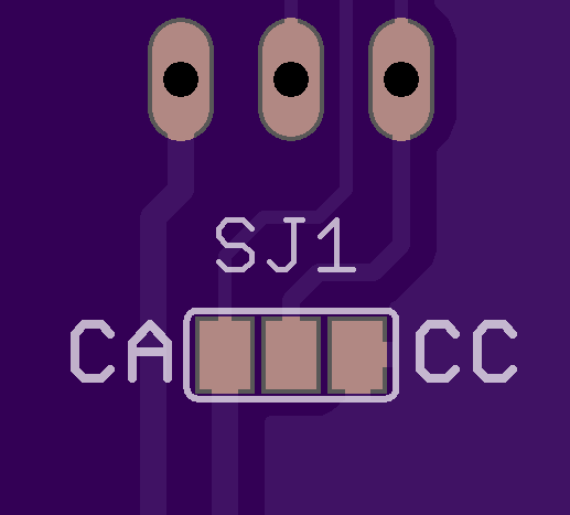
The PCB provides a solder jumper to allow the use of Common Cathode display along with a NPN transistor.
The pin assignment of the micro-controller outputs to the 16 segment display was chosen interactively during PCB design to allow straight traces and hence a single sided PCB
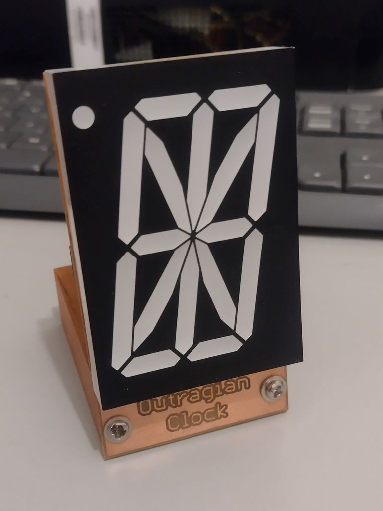
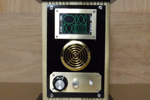
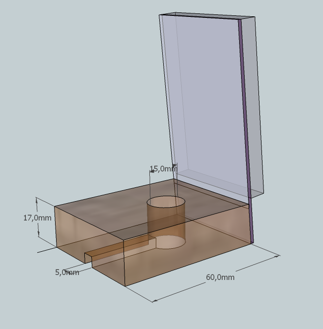
Assembly
A custom PCB was designed to hold the circuit along with a wooden base. The micro-controller and other components are mounted at the rear side of the PCB.
The circuit can be powered by a USB wall wart charger plugged directly into the micro-controller board.
The wooden base is worked to have a circular hole and a groove to pass the USB cable.
Set the Time
To set the time, press and hold the SET button until the display start to blink the Hour sequentially as the letter H, then the digit of the Tens of hours at the leftmost position, then the digit of the units of hours at the rightmost position then a short blank

If you press MODE button briefly the hour will advance by 1. A long press will cause the hour to be advanced by 10, rounding after 24 hours. Time set is done using 24 hour.
A short press on the SET button will enter the Minute adjustment, where similarly to the Hour adjustment the display will bling the letter M, then the digit of the Tens of minutes, then the digit of the units of minutes then a short blank

If you press MODE button briefly the minutes will advance by 1. A long press will cause the minutes to be advanced by 10, rounding after 60 minutes.
A short press on the SET button will enter again in the Hour adjustment.
To end the time set and return to display mode, press and hold the SET button at any time.
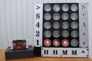
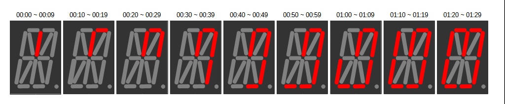
Time Interval Table
The picture below shows all the possible time intervals sequentially. The Decimal Point is lit during PM.
Once you get used to recognize the eight major intervals it is just a matter of adding 10 minutes for each of the peripheral segments, or simply ignore them and start doing your stuff when a major...
Read more »