Here is a picture of my AGC DSKY from the AGC project. It is not the prettiest thing, but it works.
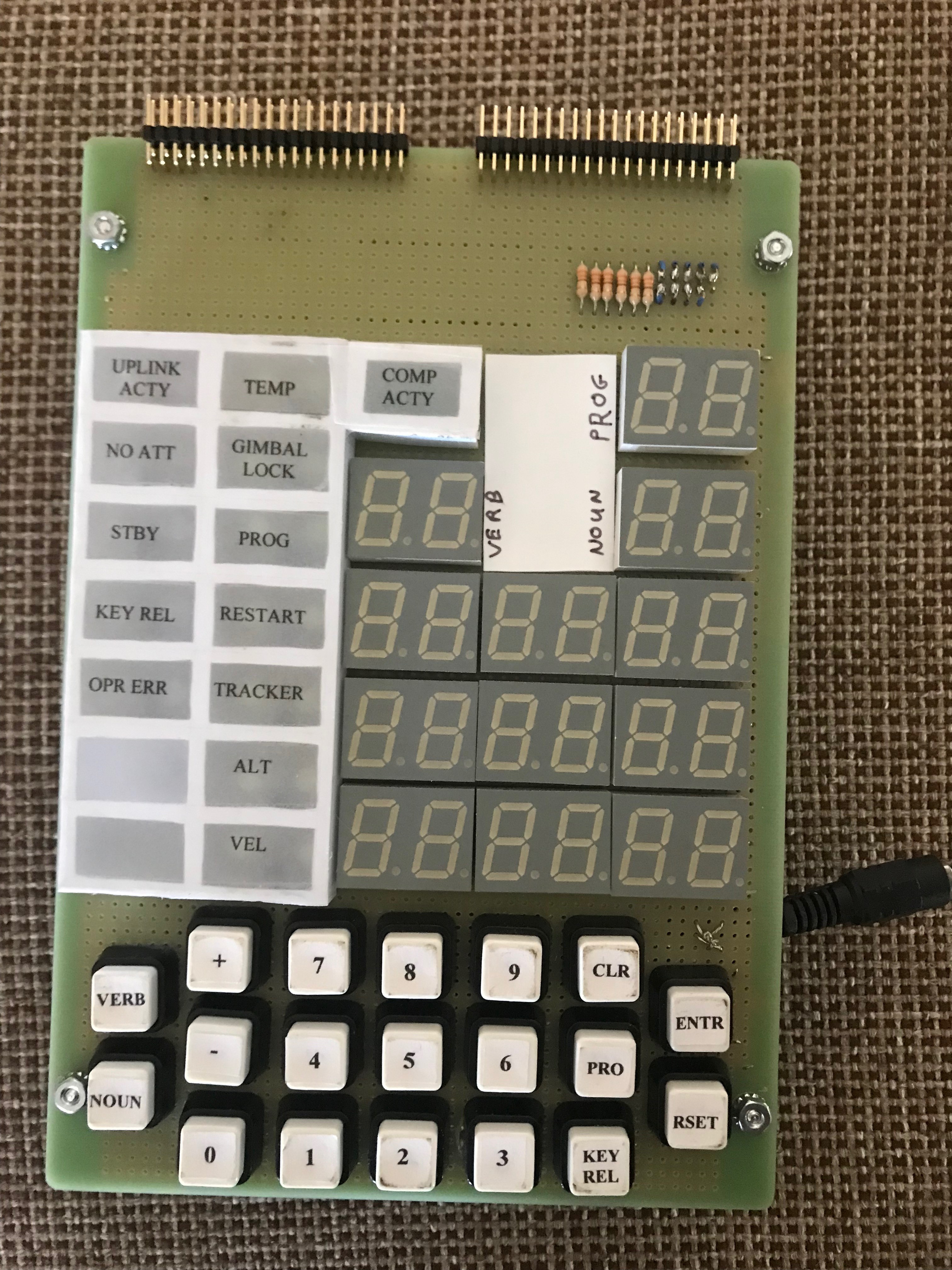
From this effort I decided this would be a much better model if I used a pair of LCD displays instead of the 7-segment LCDs and backlit indicators. Besides, the 7-segment LCDs cannot display a plus.
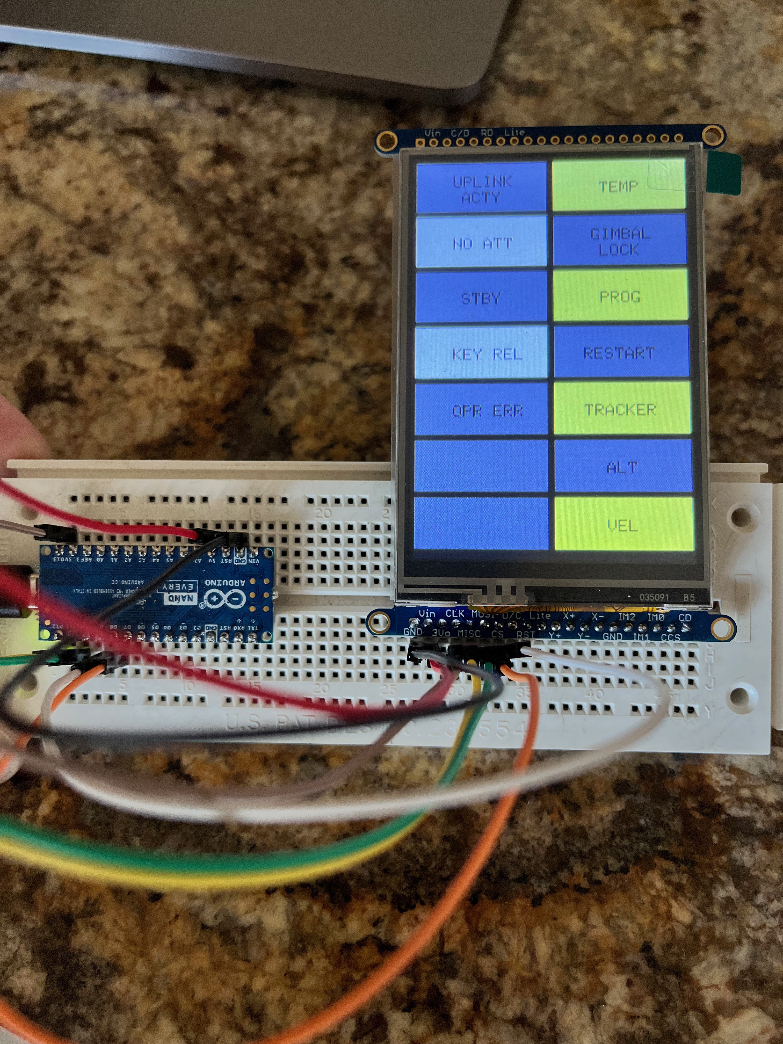
Here is the first cut at the indicators panel, much better looking than the display above. I need to work on the colors of the indicators. The display is from Adafruit, a 3.5" LCD display.
Here are the display LCD under test. I connect them using SPI and created a simple protocol to identify each one upon initialization.
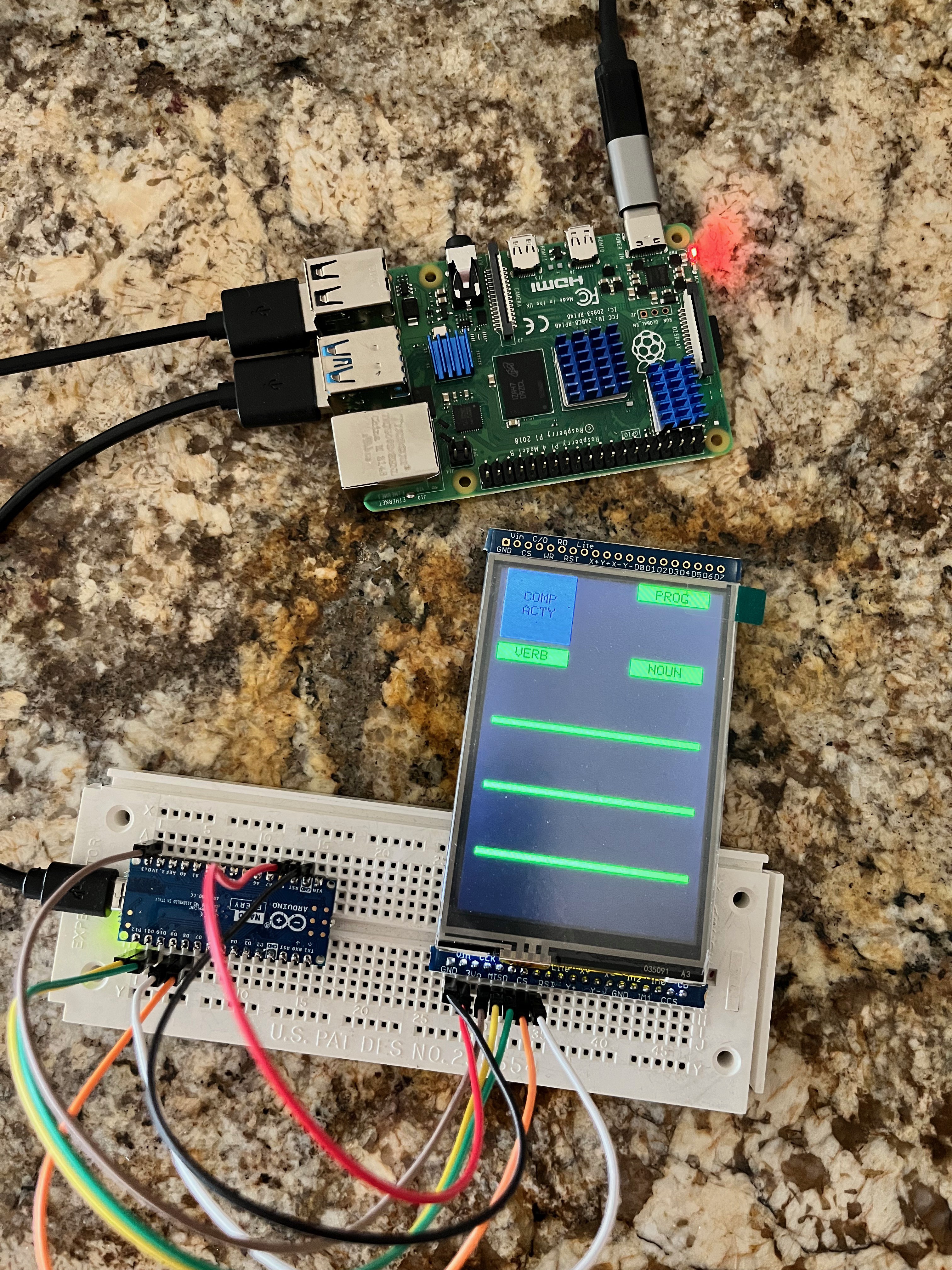
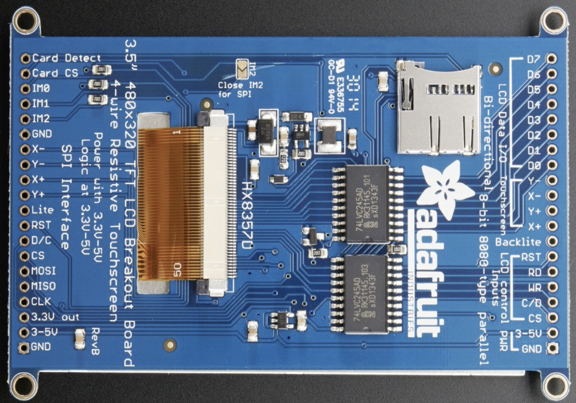
The LCD displays both connect to their respective Arduino in the same way using SPI. There is an option of using 8-bit mode as well, however that mode is seriously more complicated so for now I have gone with SPI mode. It is 2 to 4 times slower. I will have see once everything gets wired up and working if that is acceptable. For SPI mode you have to solder the IM2 jumper closed. Here are the connections between the LCD and the Arduino.
| Arduino Pin | LCD Acronym | Wire Color | Use |
| GND | GND | Black | Ground |
| 5V | 3-5V | White | Power |
| D13 | CLK | Grey | Clock |
| D12 | MISO | Purple | Microcontroller In/Serial Out |
| D11 | MOSI | Blue | Microcontroller Out/Serial In |
| D8 | CS | Green | Chip Select |
| D9 | D/C | Yellow | Data/Command Select |
| RST | RST | Orange | Reset |
| Lite | Red | Backlight on/off (on by default) |
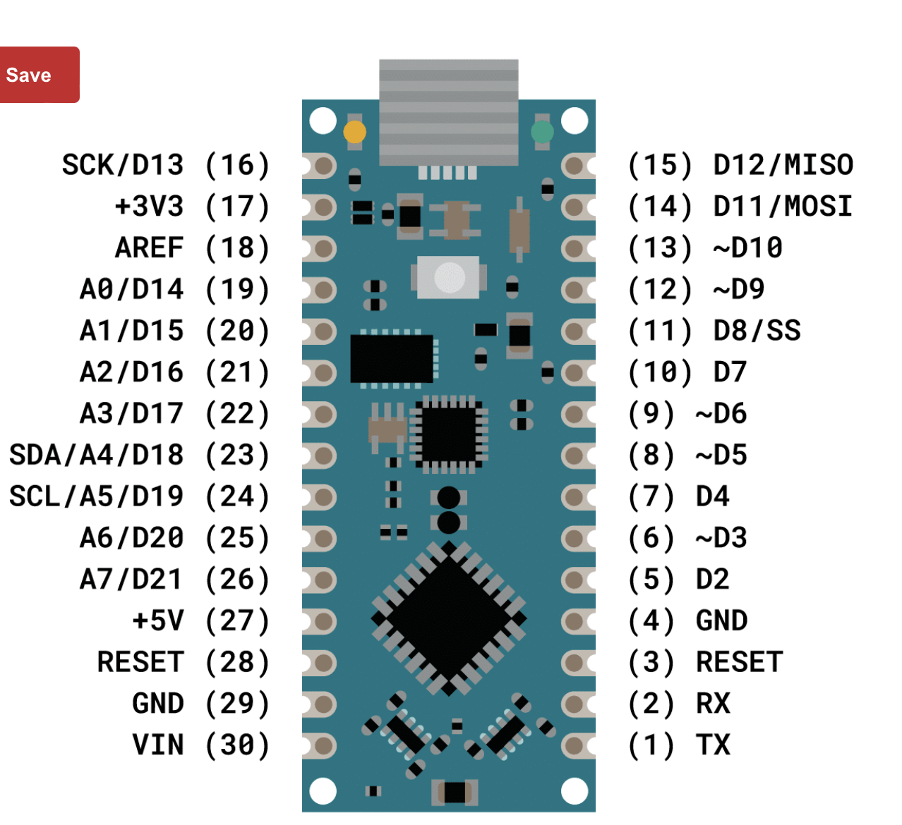
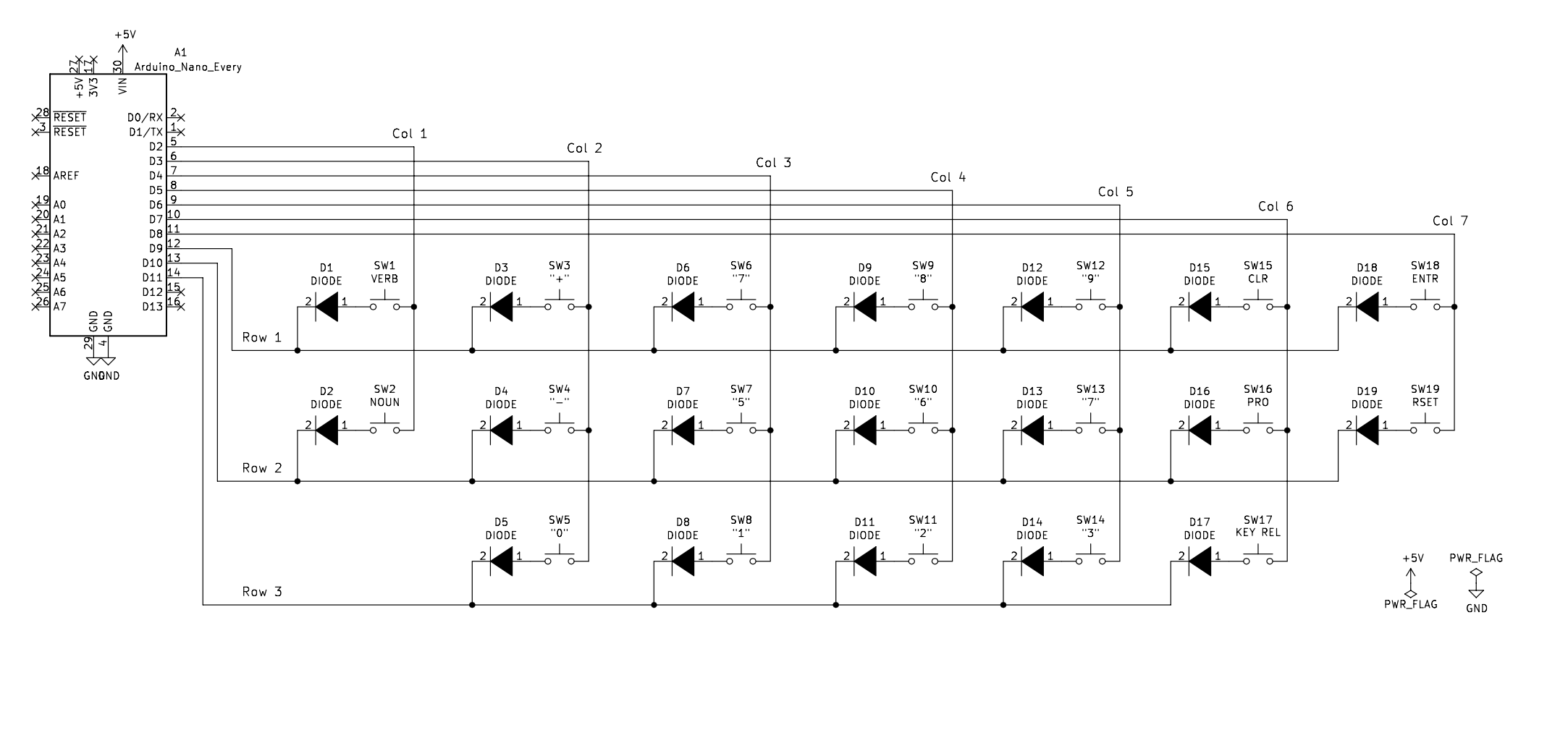
Here is an example of keyboard logic: https://www.gammon.com.au/forum/?id=14175. The DSKY has a 7x3 keyboard thus requiring 10 digital input pins. I could have connected each key to its own pin but found this solution more interesting if I ever find myself needing to implement a larger keyboard. I used the 1N4148 fast switching diodes. Each column needs a pull-up resister. Note that the Arduino has an internal pull-up resistor that can be utilized. Here is a schematic of what I wired up.
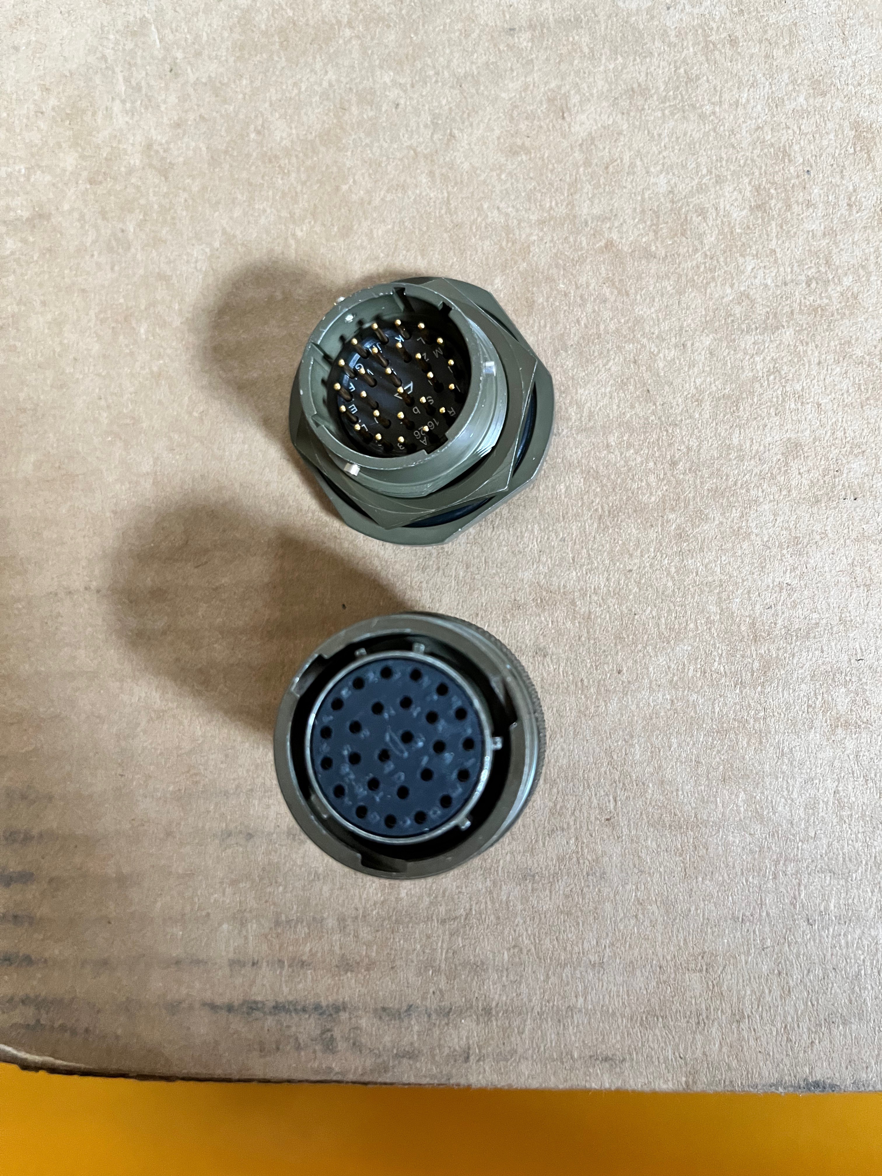
Part of making the model realistic is to use a military style jam nut connector on the back. I need 24 pins to connect the DSKY with the AGC. There are 26 pin connectors available and they look exactly like the original. The pin-outs I will use are:
Pins A-R: 15 bit Channel Bus
Pin S: CLK1: Clock 1 pulse
Pin T: RST: Reset the DSKY
Pin U: STBY: Put DSKY in Standby mode
Pin V: KBD1: Get Keyboard data
Pin W: DISP: Display data on the channel bus
Pin X: INDC: Indicator data on the channel bus
Pin Y: RPRO: Read PRO key
Pin Z: KB_STR: Keyboard data is available
Pin a: PARALM: Parity alarm
Pin b: H/W Present
Here is the jam nut and its connector, very cool.
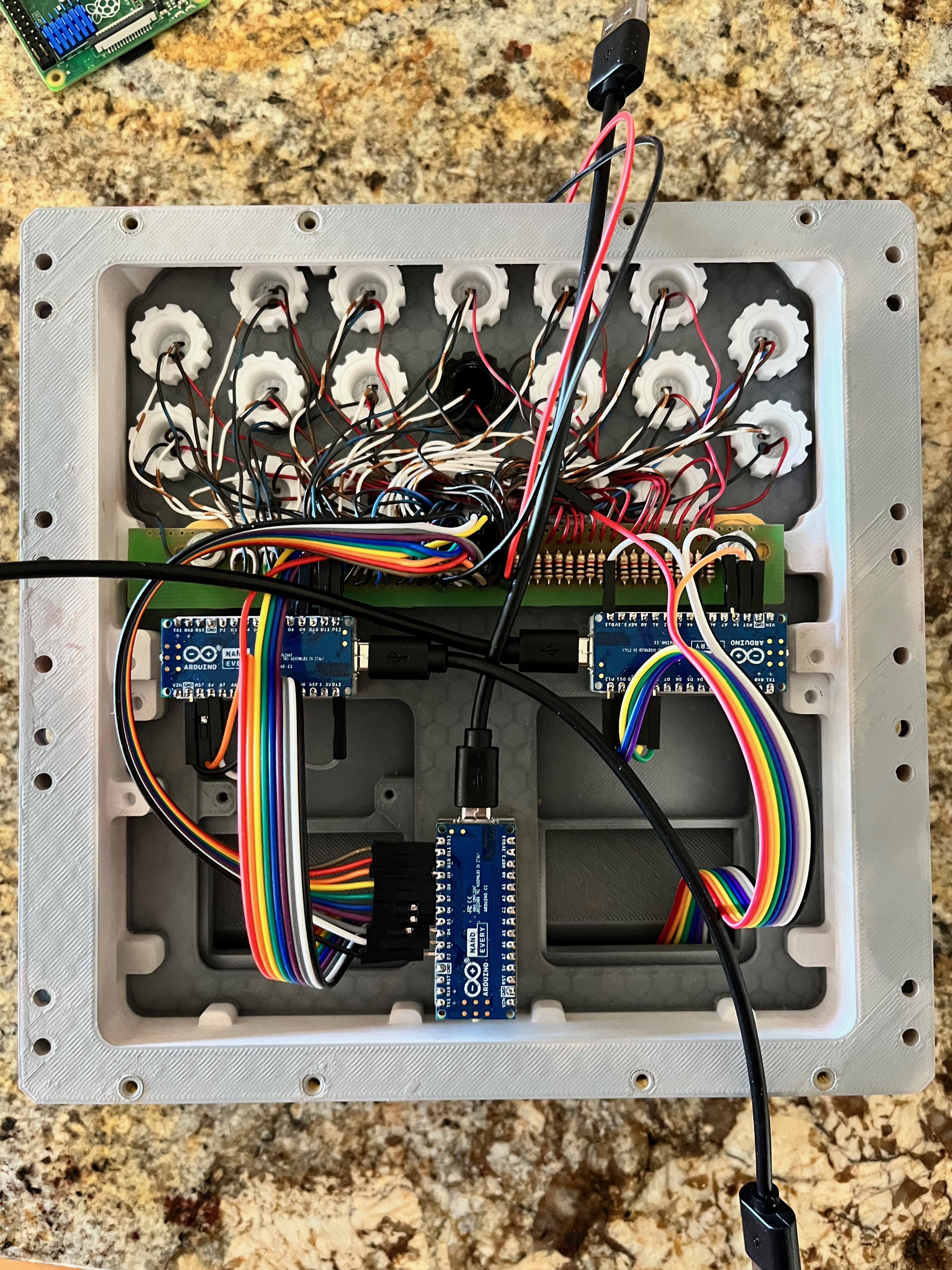
I have installed and tested the Arduinos. Here is the backside of the Front Housing showing everything assembled.
And here is the Main Housing bolted onto the front with the Raspberry Pi installed. So far I have a test program and have put the Arduino interface protocol and the Arduinos through their paces. Everything is good to go. Notice that next to the main connector I installed a micro USB port. On the original DSKY there was a bicycle tube air valve so they could fill the interior with pure nitrogen so a spark would not cause a fire.
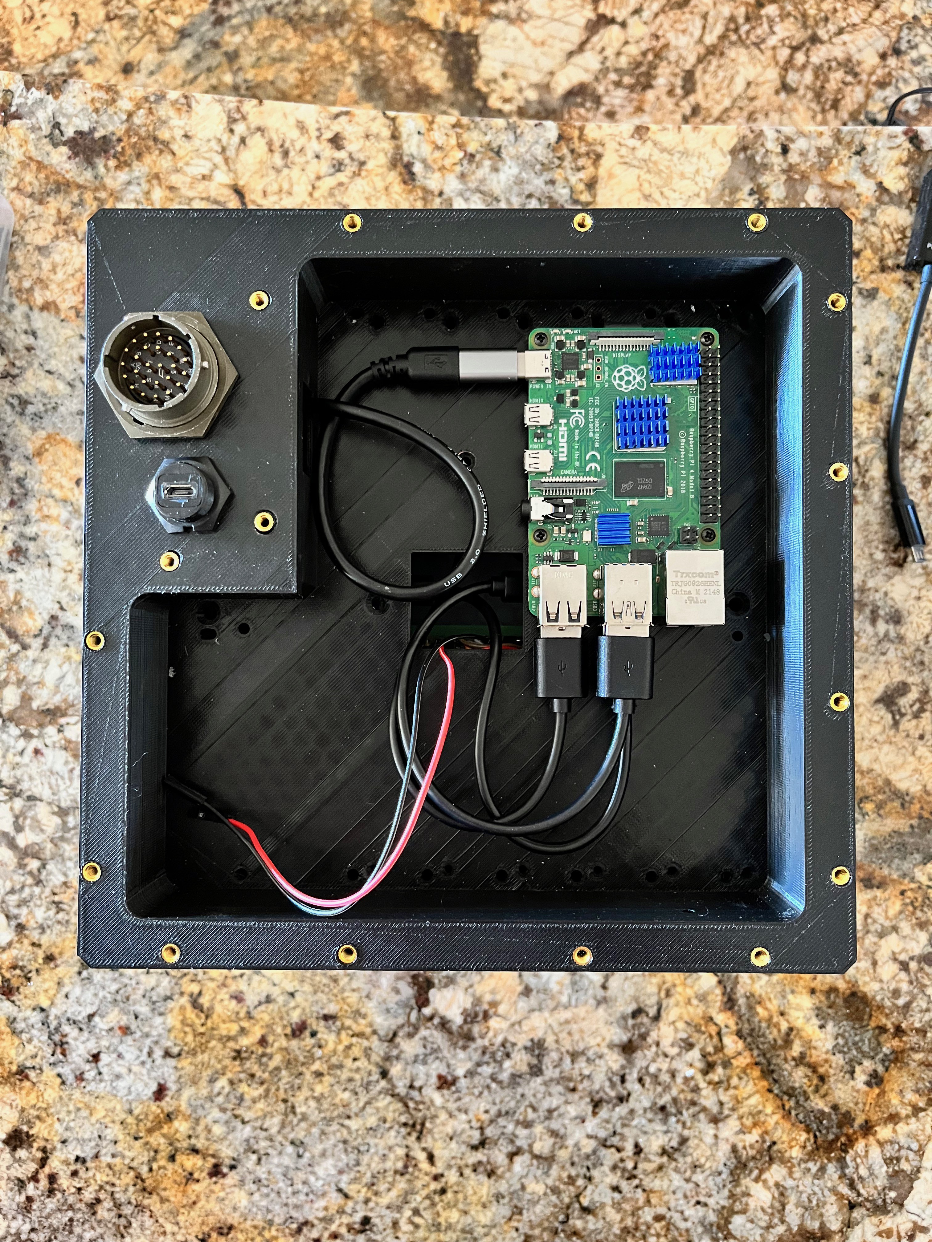
The only thing left to do hardware wise is to solder a 40-pin ribbon cable to the main connector and the 5V/GND connectors that back light the keys.
Discussions
Become a Hackaday.io Member
Create an account to leave a comment. Already have an account? Log In.