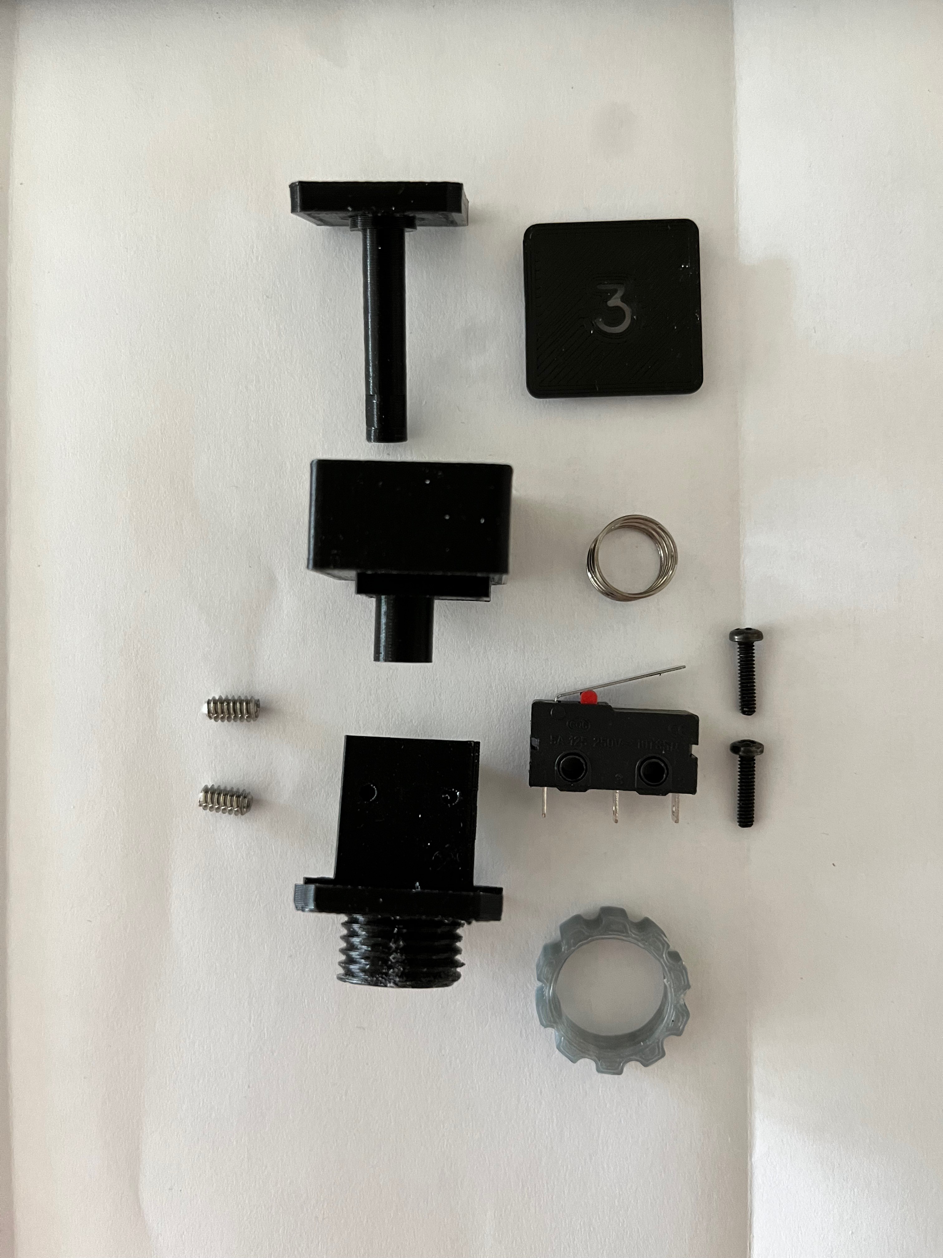
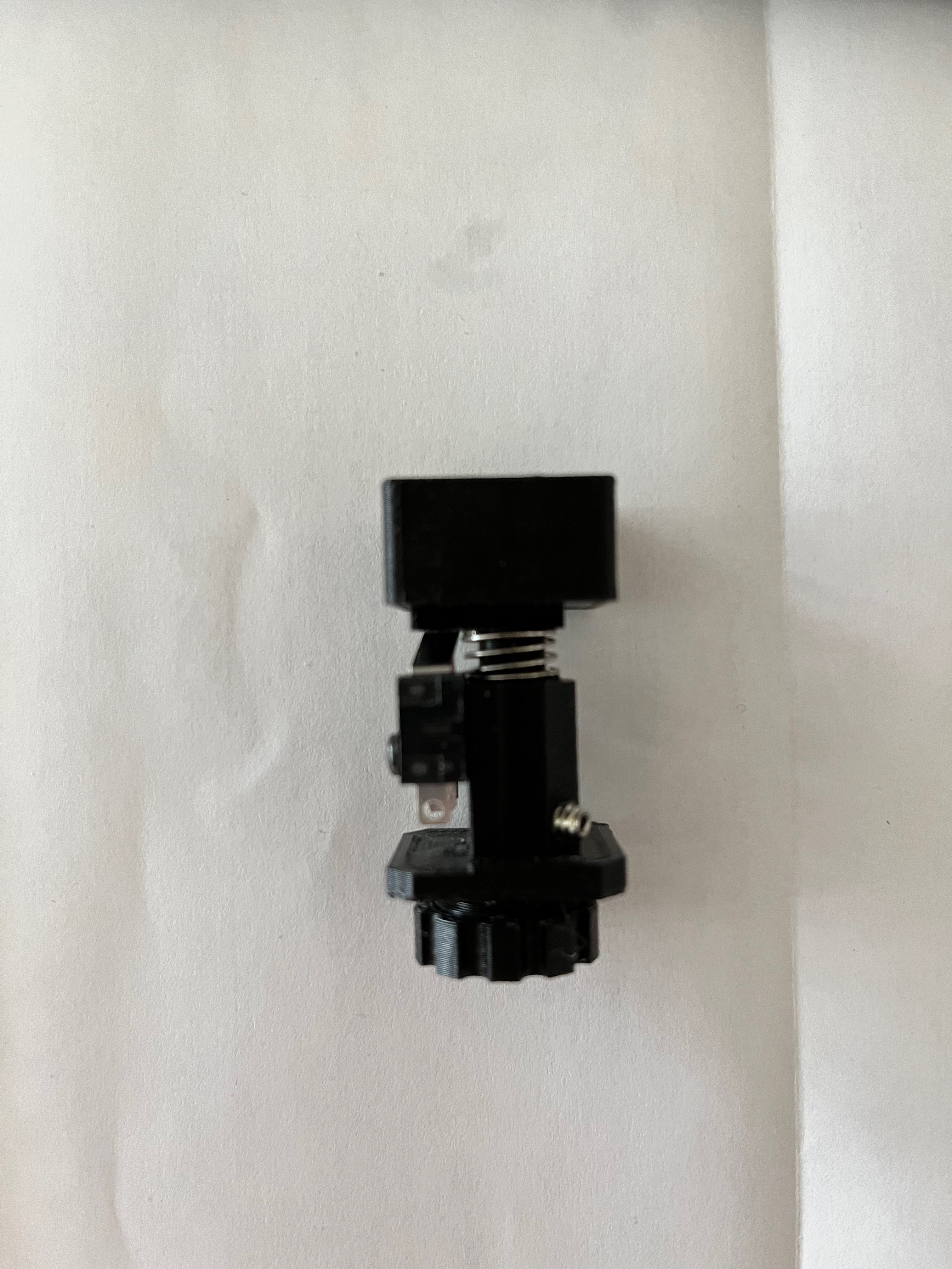
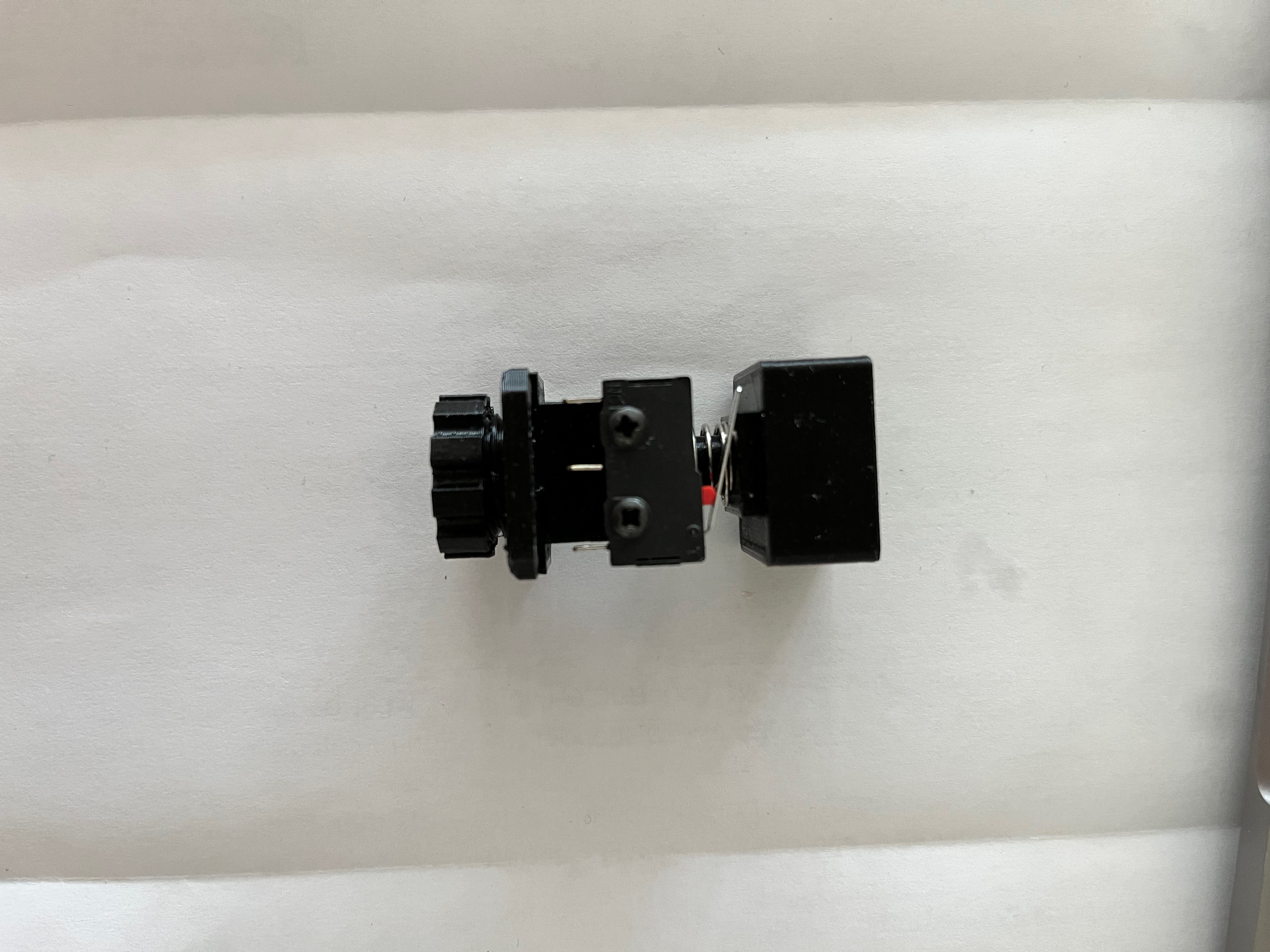
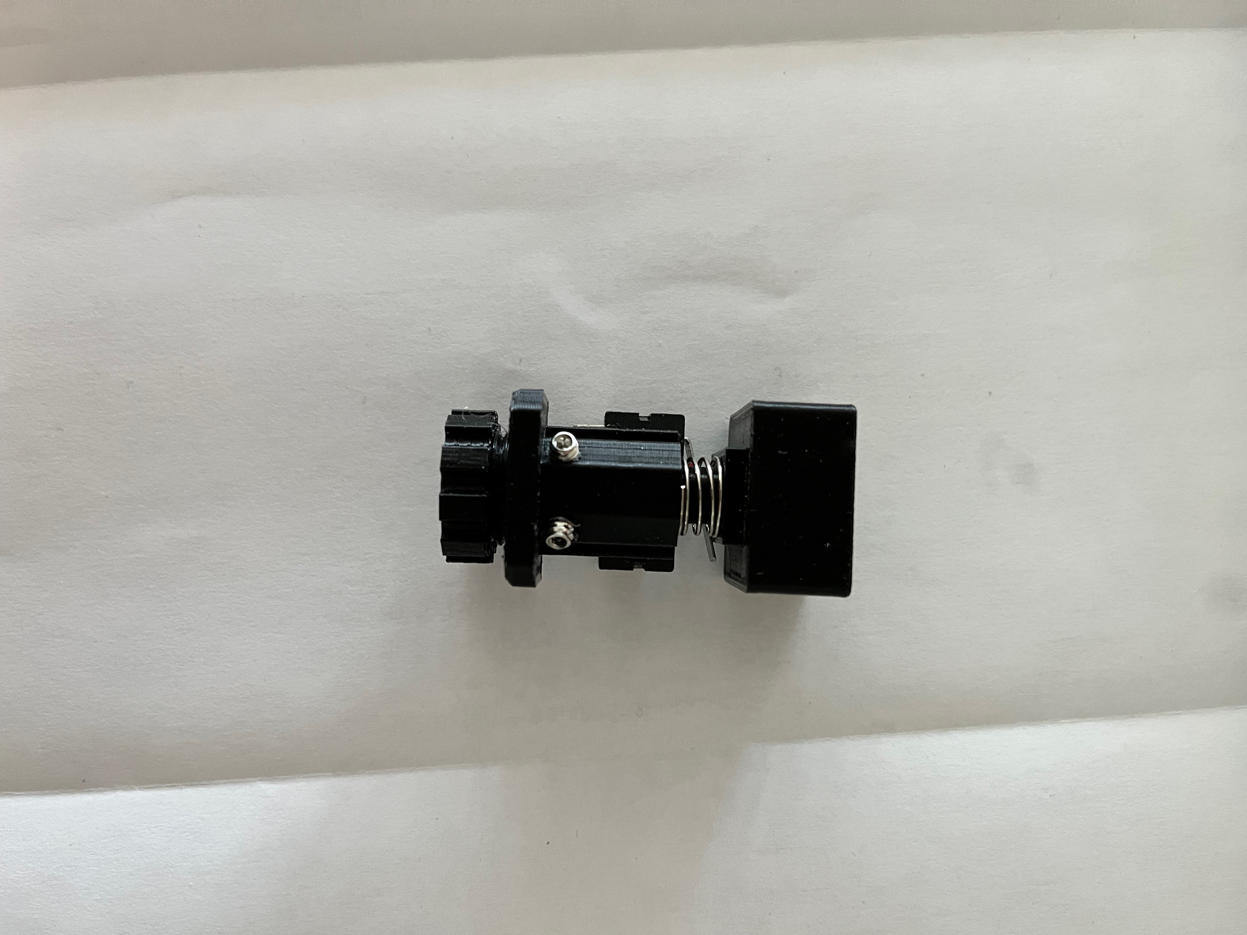
The switches are the hardest to get right. Fortunately I had a starting point thanks to M. DeSilva and his DSKY replica. From what I can gather, he put the spring inside the housing. I could not find a spring that would fit so I placed the spring on the outside. I also used screws to secure the microswitch instead of force fitting them onto plastic posts. I used 3mm white LEDs. I modified the key caps using a Gorton font I found at https://github.com/dakotafelder/open-gorton. I had to convert the .otf file to a .ttf file so it would work with Fusion 360. I used a small amount of white dye added to epoxy to fill in the back side of the key caps to make the letters white and to allow light to show through. Here are pictures of the switch pieces and three views of the switch.
 For the large nut that holds the switch assembly down I created the nut in the CAD system and then scaled it up, something like 10%, I don't remember the exact value. Without the scale up the nut was too tight a fit. To install the set screws, instead of scaling up the threads I chose to simply tap the hole for a perfect fit. I first drilled each hole to 3/32" and then tapped them with a 6-32 tap. For the smaller holes that hold down the microswitch I did not have a 2-56 tap in my set so I drilled those holes with a 5/64" bit and simply installed the screws. The plastic is pliable enough that the screw made its own threads.
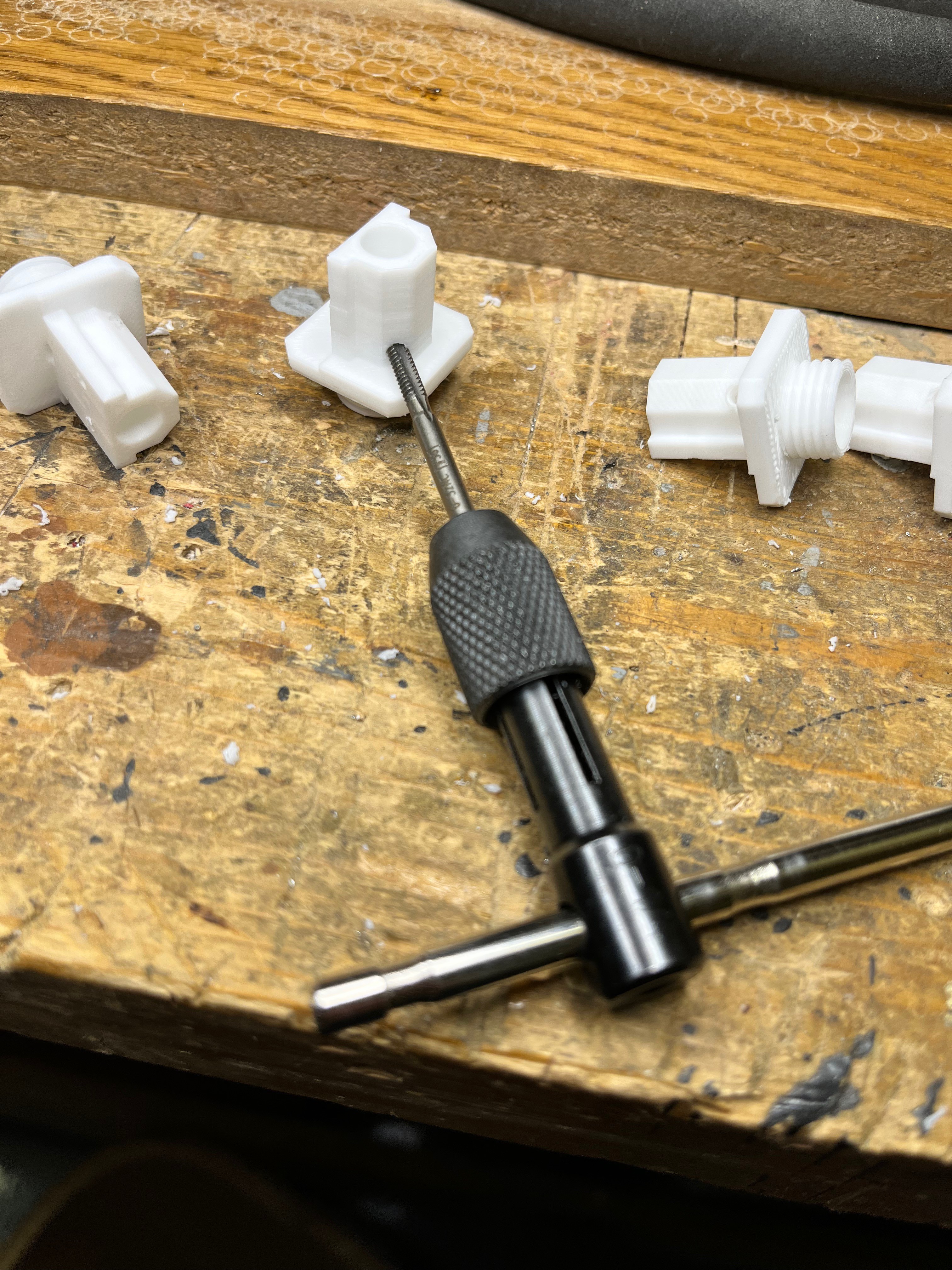
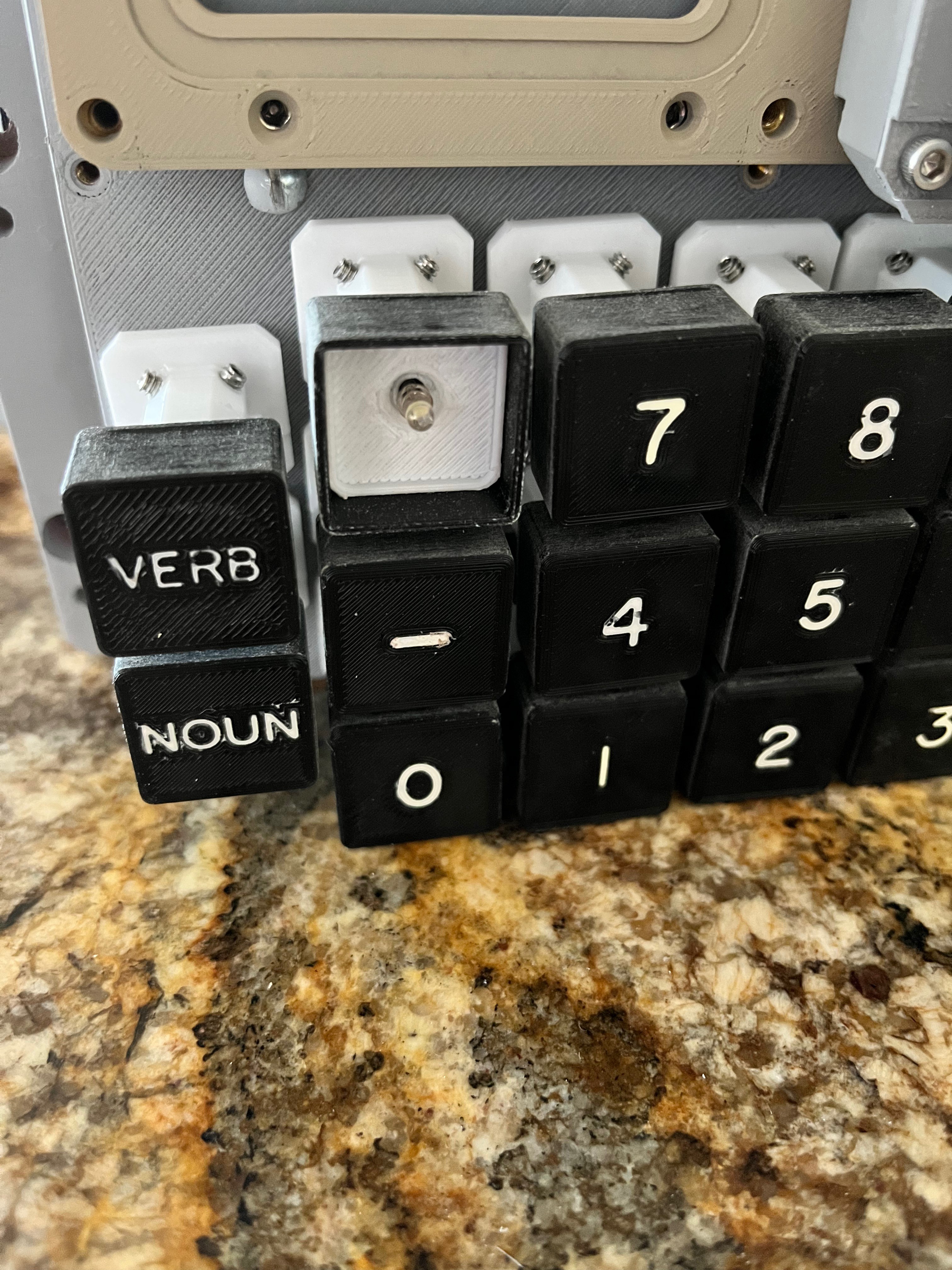
The keys are now mechanically working. I had to sand the surfaces that grate against each other to eliminate that strange rasping sound. The set screws had to be adjusted so the keys are level with the front cover. I'm not happy with the way the key covers came out, all except the + and -, those are OK. I changed the font to Gorton Heavy and scaled the size up.
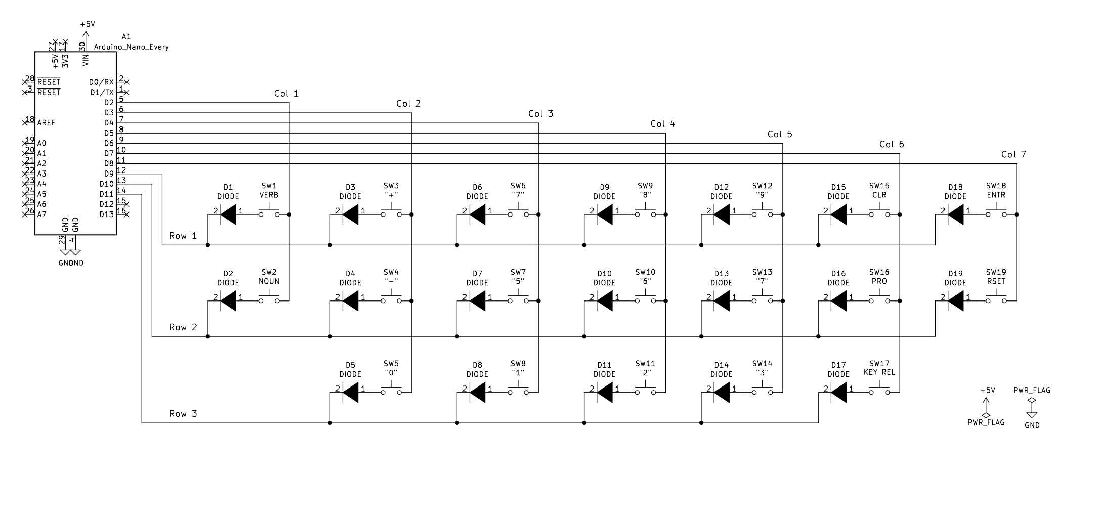
The keyboard wiring was simple enough. I chose to go with a matrix solution even though there is enough input pins on the Arduino to connect each switch to its own pin. Here is a schematic of the keyboard.
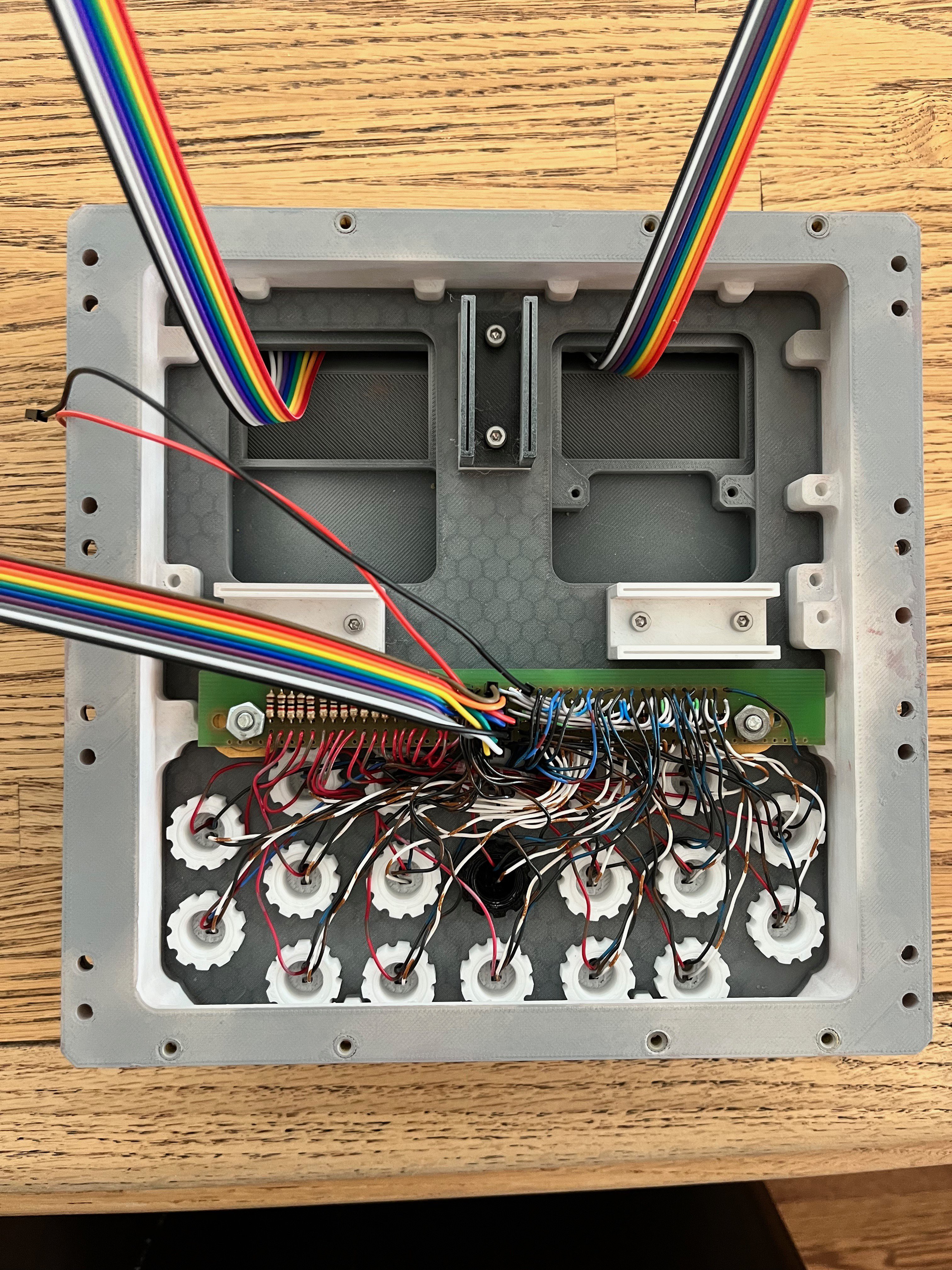
And here is a picture of the back side of the keyboard. I not only laid in 19 diodes, there is also 19 resistors to reduce the brightness of the LEDs.
I forgot to mention the LEDs. I used the smaller 3mm white LEDs. Solder two wires to the leads. You only need to shrink wrap one of the leads. The wires get pushed through the center of the switch as in the picture below.
Discussions
Become a Hackaday.io Member
Create an account to leave a comment. Already have an account? Log In.