 ElectronicABC
GERBER PCB:
https://mega.nz/file/rRxzWAKB#Jd24_dYcj03We2BB6C6Kk1vwO5IulnjRNpKDdmkClB0
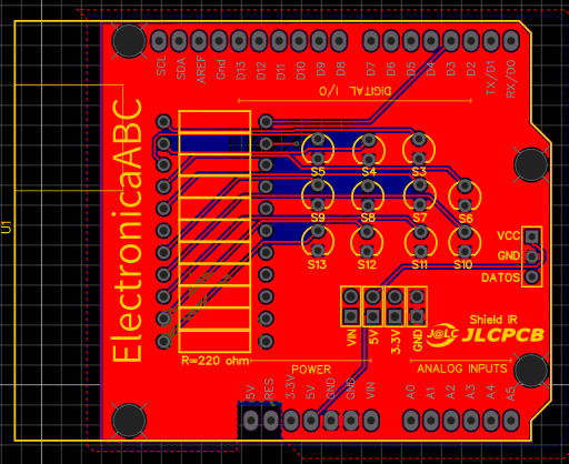
To program our ARDUINO UNO we have found the need to have a shield and facilitate the issue of external wiring. In this project we will make an ARDUINO shield where they do not need external cables because everything will be inside the PCB that we will design, therefore we will no longer opt for protoboards that with constant use sometimes make false contacts and harm us by sending errors in the tests of our circuits.
In this project we will use an IR shield that is the infrared receiver to turn on and off leds with 11 digital outputs.
#include <IRremote.h> // importa libreria IRremote
int SENSOR = 2; // sensor KY-022 a pin digital 2
void setup() {
Serial.begin(9600); // inicializa comunicacion serie a 9600 bps
IrReceiver.begin(SENSOR, DISABLE_LED_FEEDBACK); // inicializa recepcion de datos
}
void loop() {
if (IrReceiver.decode()) { // si existen datos ya decodificados
Serial.println(IrReceiver.decodedIRData.decodedRawData, HEX); // imprime valor en hexadecimal en monitor
IrReceiver.resume(); // resume la adquisicion de datos
}
delay (100); // breve demora de 100 ms.
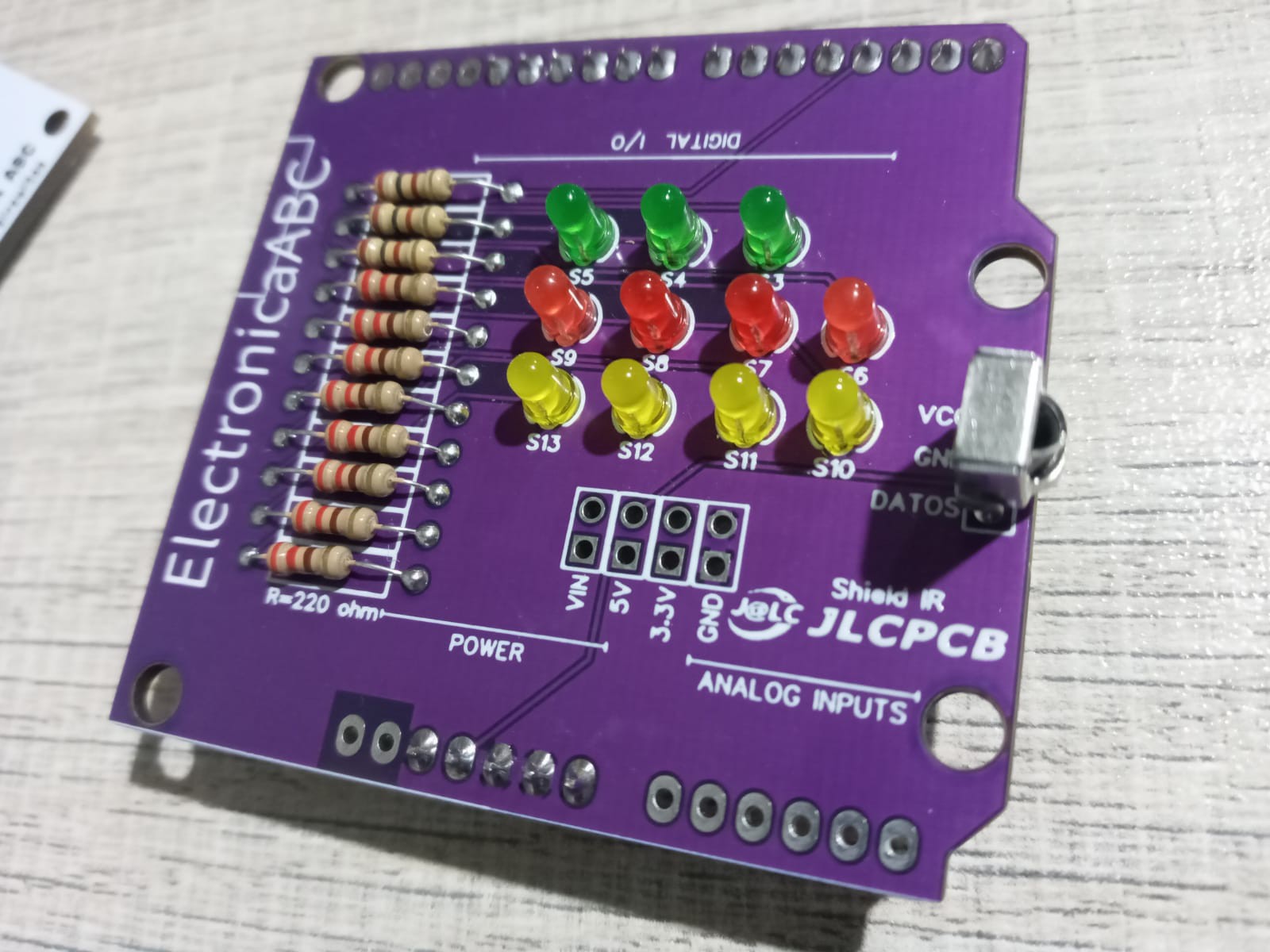
}SHIELD
It is simply a printed circuit board that is placed on the ARDUINO board and connected to it by coupling its pins without the need for any other external connection. Its function is to act as a complementary board, expanding the capabilities of the ARDUINO Base board.
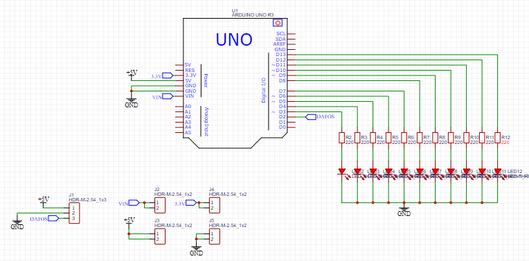
In the circuit we will first see how to receive our codes because depending on the brand of each control, the hexadecimal codes of each key can vary, so we need to be sure which codes to use to be able to turn an LED on or off. Next we will see the ARDUINO IDE source code and the electronic schematic to be able to visualize them within the ARDUINO IDE serial monitor.
IR RECEIVER
Infrared (IR) diodes work by converting electrical current into infrared light; while infrared detectors do the opposite by detecting infrared light and converting it into an electrical current. The current generated by an infrared detector is a signal indicating that this type of light exists.
Infrared is a wavelength of light that is beyond the range of human vision. This makes infrared an excellent tool for applications where light is required, but where visible light might be distracting or otherwise unwanted. The use of infrared light-emitting diodes, or LEDs, makes remote control systems possible in various projects.
The characteristics of an ir receiver are:
· With aluminum layer
· Infrared light receiver
· High sensitivity
· Infrared light receiver
· Applications: home automation, robotics, mechatronics, music, tv, video machine among others
Specs:
· Type: Infrared Receiver
· Minimum supply voltage: 2.7 V
· Maximum supply voltage: 5.5 V
· Supply Current: 1.5mA
· Maximum range: 28m
· Frequency: 38KHz
· Receiving Angle: 90°
· Minimum operating temperature: -20°C
· Maximum operating temperature: 80°C
· Number of pins: 3
ELECTRONIC COMPONENTS:
· 11 LEDS 3MM different colors
· 1 IR receiver 3 pins
· 11 resistors 220 ohm 1/4W
· Sprats 90°
· 1PCB
· 1 remote control for our tests
CHARACTERISTIC:
· VIN OUT 5V-3.3V-12V-GND
· Output voltages to power other modules
· SHIELD compact
· Distance 15 meters approximately infrared communication
And finally we will see the source code of the final tested and functional program
#include <IRremote.hpp>
#define boton_1 0xFFA25D
#define boton_2 0xFF629D
#define boton_3 0xFFE21D
#define boton_4 0xFF22DD
#define boton_5 0xFF02FD
#define boton_6 0xFFC23D
#define boton_7 0xFFE01F
#define boton_8 0xFFA857
#define boton_9 0xFF906F
#define boton_10 0xFF6897
#define boton_11 0xFF9867
#define boton_12 0xFFB04F
#define boton_13 0xFF30CF
#define boton_14 0xFF42BD


int receptor = 2;
IRrecv irrecv(receptor);
decode_results codigo;


void setup() {
  Serial.begin(9600);
  irrecv.enableIRIn();
  pinMode(3, OUTPUT);
  pinMode(4, OUTPUT);
  pinMode(5, OUTPUT);
  pinMode(6, OUTPUT);
  pinMode(7, OUTPUT);
  pinMode(8, OUTPUT);
  pinMode(9, OUTPUT);
  pinMode(10, OUTPUT);
  pinMode(11, OUTPUT);
  pinMode(12, OUTPUT);
  pinMode(13, OUTPUT);


}


void loop() {
 if(irrecv.decode(&codigo))
 {
  Serial.println(codigo.value, HEX);

  if(codigo.value == boton_1)
  digitalWrite(3, !digitalRead(3));


  if(codigo.value == boton_2)
  digitalWrite(4, !digitalRead(4));


  if(codigo.value == boton_3)
  digitalWrite(5, !digitalRead(5));


  if(codigo.value == boton_4)
  digitalWrite(6, !digitalRead(6));


  if(codigo.value == boton_5)
  digitalWrite(7, !digitalRead(7));


  if(codigo.value == boton_6)
  digitalWrite(8, !digitalRead(8));


  if(codigo.value == boton_7)
  digitalWrite(9, !digitalRead(9));


  if(codigo.value == boton_8)
  digitalWrite(10, !digitalRead(10));


  if(codigo.value == boton_9)
  digitalWrite(11, !digitalRead(11));


  if(codigo.value == boton_10)
  digitalWrite(12, !digitalRead(12));


  if(codigo.value == boton_11)
  digitalWrite(13, !digitalRead(13));


  if(codigo.value == boton_12){

  digitalWrite(13,HIGH);
  delay(500);
  digitalWrite(13,LOW);
  delay(500);
  digitalWrite(13,HIGH);
  delay(500);
  digitalWrite(13,LOW);
  delay(500);
  digitalWrite(13,HIGH);
  delay(500);
  digitalWrite(13,LOW);
  delay(500);
  }
  if(codigo.value == boton_13){

  digitalWrite(3,HIGH);
  digitalWrite(4,HIGH);
   digitalWrite(5,HIGH);
    digitalWrite(6,HIGH);
     digitalWrite(7,HIGH);
      digitalWrite(8,HIGH);
       digitalWrite(9,HIGH);
        digitalWrite(10,HIGH);
         digitalWrite(11,HIGH);
         digitalWrite(12,HIGH);
         digitalWrite(13,HIGH);}

   if(codigo.value == boton_14){

  digitalWrite(3,LOW);
  digitalWrite(4,LOW);
   digitalWrite(5,LOW);
    digitalWrite(6,LOW);
     digitalWrite(7,LOW);
      digitalWrite(8,LOW);
       digitalWrite(9,LOW);
        digitalWrite(10,LOW);
         digitalWrite(11,LOW);
         digitalWrite(12,LOW);
         digitalWrite(13,LOW);
         }


  irrecv.resume();
 }
 delay(100);
}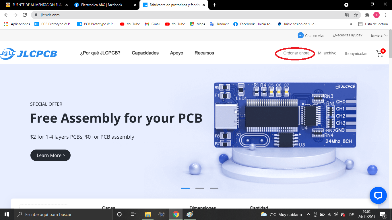
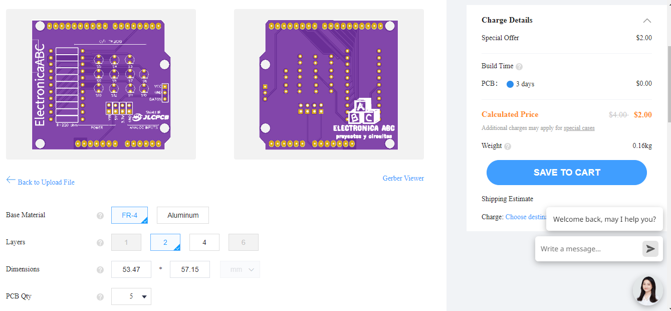
We thank JLCPCB for professional PCBs
Order your PCBs here
5PCBS AT $2
GERBER PCB:
https://mega.nz/file/rRxzWAKB#Jd24_dYcj03We2BB6C6Kk1vwO5IulnjRNpKDdmkClB0