 ElectronicABC
GERBER PCB:
https://mega.nz/file/Ld4WVZTJ#6T6i2Nx7x5_o8kfZtJZopY70kUnhQq6tAgHlsXSePVY
This project is a sequence of SHIELDS for ARDUINO UNO that will help us a lot in our tests.
A shield is simply a printed circuit board that is placed on the ARDUINO board and connects to it by coupling its pins without the need for any other external connection. Its function is to act as a complementary board, extending the capabilities of the ARDUINO Base board. The shields can be compatible with different types of ARDUINO boards, most of them are designed to operate with ARDUINO UNO boards.
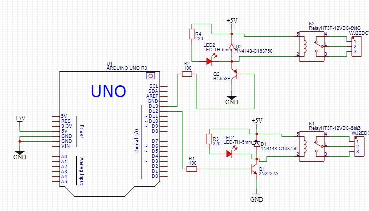
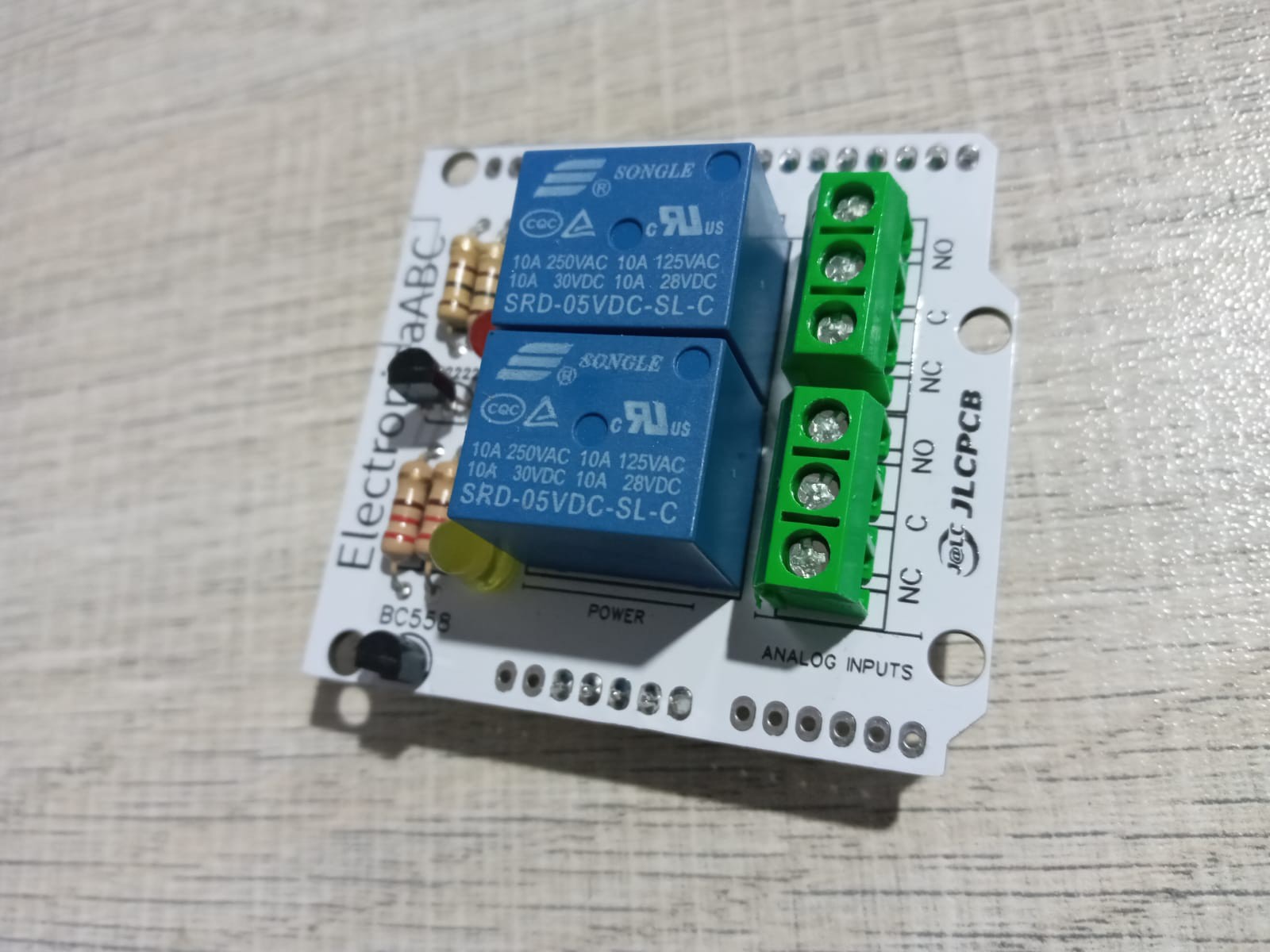
In this project we do not use protoboards, because of the constant use of its pins, these could malfunction, so I proposed to make the following SHIELD of RELE 2 channels. We can see that in the market RELE modules of different channels are sold but in this project we will not use the famous wiring but we will implement a SHIELD to use it directly from our ARDUINO and test them with different programs.
Here I leave the source code and schematic diagram.
RELE
Within the wide variety of projects that we can do with ARDUINO, we may want to control high voltage or high amperage components, such as light bulbs or water pumps, which cannot be managed directly with ARDUINO. In these cases it is necessary to use Relays or Relays, these devices allow to control high voltage loads with a small signal.
The module has 1 high quality relay, manufactured by Songle, with capacity to handle loads up to 250V/10A. The relay module has a power indicator LED (red) and an activation indicator LED (green). This module, unlike the relay modules of 2 or more channels, does not have optocouplers, instead the relay activation is by means of a transistor. The module design makes it easy to work with ARDUINO, as well as with many other systems such as Raspberry Pi, ESP8266 (NodeMCU and Wemos), Teensy and Pic. This Relay module activates the normally open output (NO: Normally Open) when receiving a logic "0" (0 Volts) and deactivates the output with a logic "1" (5 Volts). For programming the use of Relays with ARDUINO it is recommended to use timers with the "millis()" function and thus not use the "delay" function that prevents the system to continue working while a relay is activated/deactivated.
Among the loads that can be handled are: light bulbs, light fixtures, AC motors (220V), DC motors, solenoids, solenoids, solenoid valves, water heaters and a variety of other actuators. It is recommended to make and verify the connections before feeding the circuit, it is also a good practice to protect the circuit inside a case.
NOTE: 220V AC VOLTAGE IS VERY DANGEROUS! IF HANDLED INCORRECTLY IT CAN CAUSE DEATH! THAT IS WHY WE MUST BE VERY CAREFUL WHEN MAKING THE CONNECTIONS. NAYLAMP MECHATRONICS IS NOT RESPONSIBLE FOR ANY DAMAGE CAUSED BY THE MISUSE OF THIS MODULE.
int RELE = 12;			// pin IN de modulo a pin digital 12 de Arduino int RELE2 = 13;         // pin IN de modulo a pin digital 13 de Arduino


	void setup(){

	  pinMode(RELE, OUTPUT);	// pin 12 como salida      pinMode(RELE2, OUTPUT);	// pin 13 como salida

	}


	void loop(){

	  digitalWrite(RELE, LOW);	// activacion del modulo de rele con un nivel alto      digitalWrite(RELE2, LOW);	// activacion del modulo de rele con un nivel bajo

	  delay(5000);			// demora de 5 seg.

	  digitalWrite(RELE, HIGH);	// apagado del modulo de rele con un nivel bajo      digitalWrite(RELE2, HIGH);	// apagado del modulo de rele con un nivel alto

	  delay(5000);			// demora de 5 seg.

	}
TECHNICAL SPECIFICATIONS
- Operating Voltage: 5V DC
- Control Signal: TTL (3.3V or 5V)
- No. of Relays (channels): 2 CH
- Maximum Capacity: 10A/250VAC, 10A/30VDC
- Maximum current: 10A (NO), 5A (NC)
- Action time: 10 ms / 5 ms
- To activate NO output: 0 Volts
ELECTRONIC COMPONENTS:
- 2 relay 5vdc
- 1 NPN transistor
- 1 pnp TRANSISTOR
- 2 DIODE 1N4148
- 2 RESISTORS 220 ohm 1/2w
- 2 resistors 100 ohm 1/2w
- 2 LED DIODES 5MM
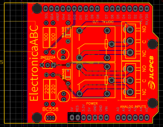
- 1 PCB
PCB CHARACTERISTICS:
- VOUT 220VAC
- I MAX 100 mA
- Shield 2 relay channels
- Different channels, one active with "0" and the other with "1".

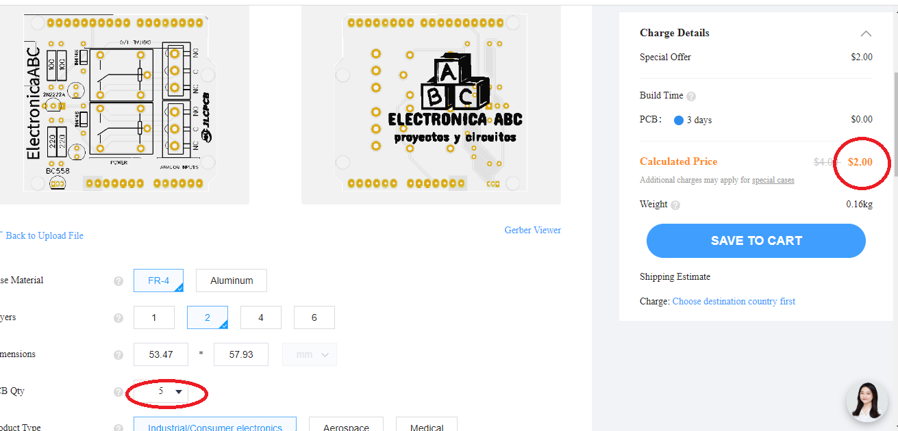
We thank JLCPCB for professional PCBs
Order your PCBs here
5PCBS AT $2
GERBER PCB:
https://mega.nz/file/Ld4WVZTJ#6T6i2Nx7x5_o8kfZtJZopY70kUnhQq6tAgHlsXSePVY