 ElectronicABC
GERBER PCB
https://mega.nz/file/nERhUSLb#z1P4hNOccH4jQYI4_iCEwMAkhxcKEVOFvEZjLT8Vnr4
DATASHEET TDA2003A:
https://mega.nz/file/KIA3CBSL#92qu_hKXFkJ83NCSCD_69nYmstz8fH77L3DrNCxn7F8
Many times I have wanted to make an audio amplifier of very good quality but there are many plans with very basic integrated circuits so I have searched and I have found an IC that has an excellent audio quality and with a supply voltage of 12VDC.
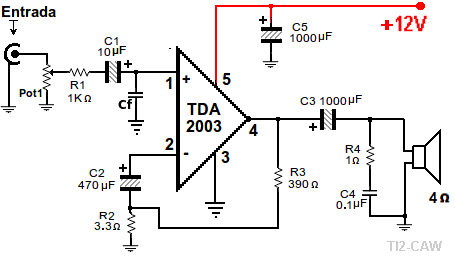
One of the easiest amplifiers to build (I will show the diagram and drawing).
Using a TDA2003 and a few components we have a good amplifier that can work to amplify the audio output of our computer or as a test amplifier.
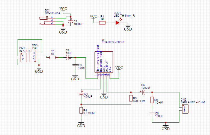
Connection diagram of the TDA2003
According to the manufacturer the TDA2002 is 8W and the TDA2003 is 10W.
Connections, component values and voltage are the same.
For test instruments they can work with 9 Volts, as power amplifiers they work perfect with 14 volts, and it is better not to reach 18V.
Electronic components:
Pot1 is a logarithmic potentiometer from 10K to 50K.
C1 if not for "Woofer" can be 1 or 2.2 microfarads from 10 volts and up.
If you want better bass it can be 10 microfarads.
Cf can be 470 picofarads, if there is noise it can be of higher value.
trying not to sacrifice high notes (treble or trills).
R1 is 1000 ohms, it can be small (less than 1/8W).
R2 is 3.3 ohms (less than 10 ohms*, greater than 2)
R3 is 390 ohms (can be: R2 x 100)
If we want more gain we increase the value of R3.
C3 1000 microfarads 16 volts (at 10 volts works well)
R4 1 ohm (brown, black, golden, golden)
C4 0.1 microfarad, some represent it as 104.
C5 1000 microfarads 16 Volts or higher.
If the source is well rectified and there is not much wire distance it can be 470 microfarads.
Important note:
If it is to be connected to the output of the computer or a player, noise can be produced by too much gain or sensitivity of the amplifier. Noise may be produced by too much gain or sensitivity of the amplifier. Then it is necessary to increase the R2 value, even more than 33 ohms.
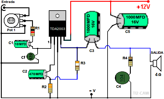
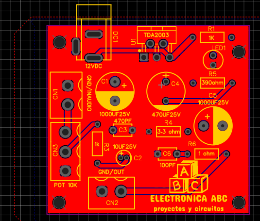
Drawing of the amplifier with TDA2003:
In this graphic we can see the placement of the components of this amplifier, we must pay attention that the negative connection to the current or ground is only mixed in the leg 3 of the integrated circuit, if we mix the ground of the speaker and the input can produce noise and unwanted oscillations.
Since it is only one channel, 2 channels must be made to use it in stereo.
The power supply to be used for this project must be capable of supplying 2 amps.
The heat dissipation of the integrated circuit is very important, since the temperature determines the life of the integrated circuit.
We can add a fan of the type used in computer power supplies and to avoid introducing noise we add a resistor and a capacitor.
Computer fans do not consume much power and the resistance can be from 22 to 47 ohms, as long as the fan starts up well.
I build this amp a lot, sometimes to replace a discontinued amp or for projects where I need one that sounds loud enough.
But when I really want to make noise, I use one of the 20 Watts (bridged) amplifiers.
There are integrated circuits that have 2 bridged outputs, and even 4 that some modern car radios use.
They are usually not very cheap, but they have almost no components, so they are very easy to manufacture.

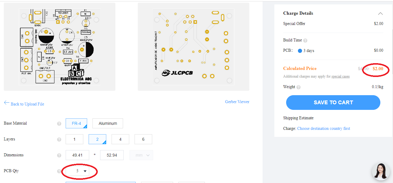
We thank JLCPCB for professional PCBs
Order your PCBs here
5PCBS AT $2
GERBER PCB:
https://mega.nz/file/nERhUSLb#z1P4hNOccH4jQYI4_iCEwMAkhxcKEVOFvEZjLT8Vnr4
 Ghani Lawal
 Lithium ION
 ElectroBoy
 Sagar 001