 kaimac
I redesigned everything so here's another overview.
- 8-bit computer with a 16-bit address bus, probably built on Eurocards
- Simplicity > performance, but I want it to be a target for a high-level language - it's not "minimal"
- Starting off with just a UART interface - would like to add other peripherals later (floppy disk, maybe graphics)
- Clock speed in the few MHz range
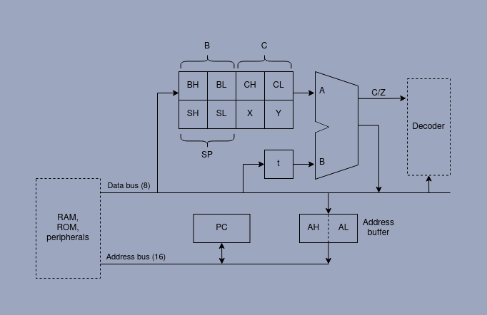
There are eight 8-bit registers, six of which can be combined into three logical 16-bit registers - B, C and SP (stack pointer). T is a temporary register containing the second operand for any ALU operations.
Instruction set
To keep instruction decoding simple, all instructions consist of 1 byte of opcode, followed by 0, 1 or 2 bytes of immediate data. This forces some trade-offs in the ISA. Some simple operations require multiple short instructions, but this fact is largely hidden by the assembler.
For example, ALU operations either add an immediate value to a register, or add the contents of T:
add x, #32     ; this is a single instruction
add x, y       ; this is accepted by the assembler
               ; and turned into:
mov t, y       ; 69
add x, t       ; 70
Memory access requires a separate instruction to load the address buffer A:
ldx sp+31      ; becomes:

adr sp+31      ; 06 1f
ldx            ; 20
There are no interrupts to worry about on this system, so the values in A and T don't need to be saved, or given much thought to. A smart assembler/compiler (or human) might be able to keep track of them to avoid redundant writes.
Not super performant, but I quite like the simplicity of it.
Addressing modes
The ISA design allows for many addressing modes. The adr instruction loads the address buffer, and there is one version of adr for each addressing mode - 20 in total:
adr ADDR            ; absolute 16-bit address
adr b               ; addr = contents of B register
adr c               ; addr = C
adr sp              ; addr = SP
adr b/c/sp + #L     ; B or C or SP, plus 8-bit literal offset
adr b/c/sp + #LL    ; B/C/SP plus 16-bit offset
adr b/c/sp + x/y    ; B/C/SP plus X or Y
adr sp + b/c        ; SP plus B or C
adr b + c           ; B plus C
adra                ; indirect: A = mem[A]
As above, when writing assembly the adr instruction would not normally be used directly - instead these addresses are used as operands in other instructions:
ldb sp+4       ; load b from stack pointer + 4    (3 byte instruction: adr #4 ldb)
add x, [c+y]   ; x = x + mem[c+y]                 (3 bytes: adr ldt add)
ALU
The usual stuff - add and subtract with or without carry, inc/dec, compare, and three logic operations (and, or, xor). The ALU will be implemented with two EEPROMs.
Assembly example
The assembler has has native support for Pascal-like strings - no null-termination here!
            mov b, #string1
            call prints
            halt
string1     .string "Hello, world!"


UART = $f000
;print a length-prefixed string (max len 255)
; b   string to print
; xyc clobbered

prints      mov c, #UART
            ldx b           ; x = string length (8 bits)
psloop      inc b
            ldy b           ; read char from string
            sty c           ; write char to uart
            dec x
            jnz psloop
            ret
Discussions
Become a Hackaday.io Member
Create an account to leave a comment. Already have an account? Log In.