 sandy
sandy3D-Scanner-based-on-IR-sensor
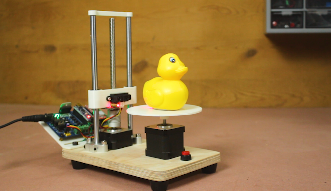
Hello friends in this project I have made a 3D scanner machine, basically this machine have a sharp IR sensor which measure the distance between sensor and surface of object
at every 1.8 degree angle in this way it takes 200 readings in 1 full turn of object then sensor itself lift up by 1 mm
and again take 200 readings in this way a point cloud data is stored in memory card and the point cloud file then imported in MeshLab software and here we can convert into mesh and we can export it STL format also.
Component reuired
Arduino Nano Custom PCB 2 Stepper motor 2 A4988 stepper driver sharp IR sensor Laser diode 8mm Smooth rod T8 Lead screw 3D printed parts 8mm linear bearing
Circuit diagram
I have used my multipurpose PCB for Arduino based resistor reel cutting machine project. If you want to have this PCB Please find the Gerber file from the link below so that you can order your own PCB I suggest you JLCPCB.COM to choose your PCB manufacturer they really have very good service and low price Multipurpose PCB link https://oshwlab.com/sharmaz747/multipurpose-pcb
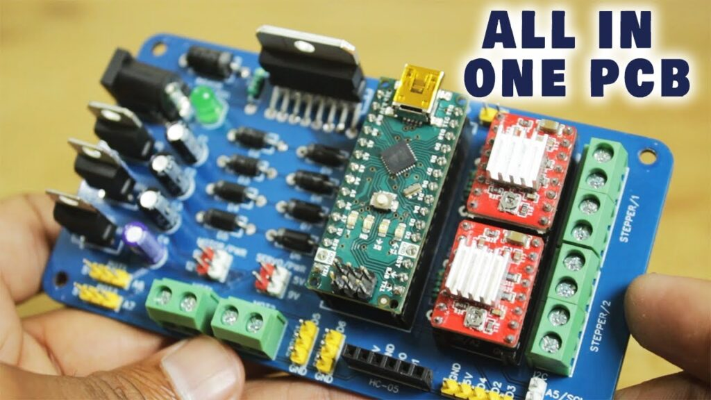


Making such projects without PCB is night mare yes trust me you cannot get wanted result and professional touch in your project if you ignore PCB So some days back I have developed my Multipurpose PCB. This PCB is used to build wide range of arduino projects
followings are the some features of PCB
- Wide range of power input 9V to 24V DC
- Cross polarity protection
- DC motor voltage selection 9V or 12 V DC
- Servo motor voltage selection 5V or 9V DC
- Manual microstepping setting for stepper motor
- Power indication LED
- L298N IC for heavier DC motor
- ON board 5V and 9V regulator no need to arrange different power sources
- Header pins and screw terminals for easy connections
List of the Components you can connect to the PCB
- 2 DC motor ( 9V to 24V DC)
- 2 Potentiometer
- 2 Servo motors ( 5V to 9V DC)
- 1 Serial device (BT module, HMI, Communication module, RX, TX)
- 1 Encoder (2 interrupt pin & 1 PB pin)
- 1 I2C device (SCL/SDA Device, display, MPU6050 etc)
- 2 Stepper motors
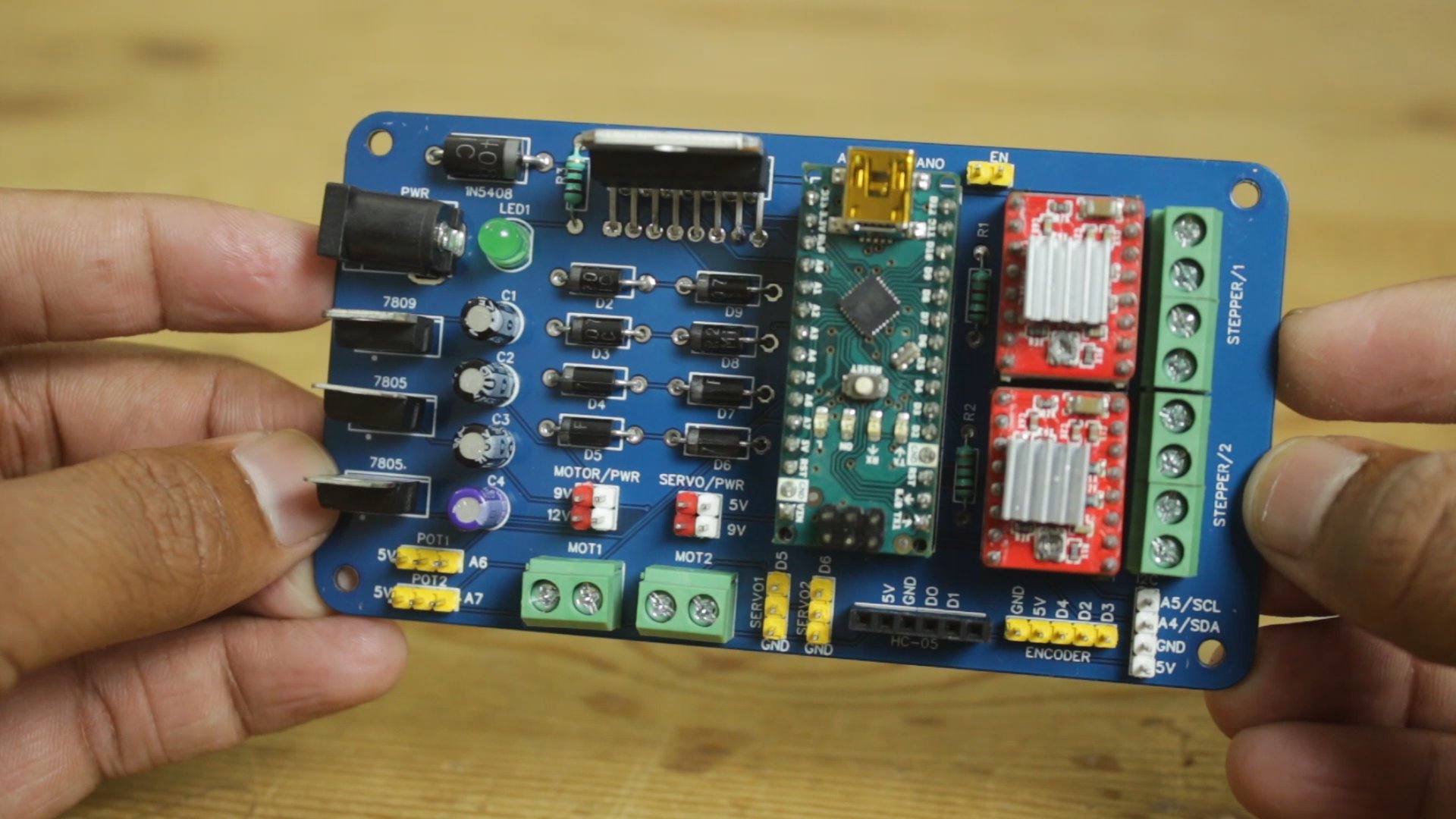

I have design circuit and PCB in easyEDA and ordered PCB from JLCPCB
This is the link of PCB editabl file
If you seriously need quality PCB quickly in your hand then you must have to try JLCPCB PCB manufacturing service. They have Special offer of $2 for 1-4 Layer PCBs, free SMT assembly monthly. If you get yourself registered today at JLCPCB you get 30$ welcome coupon from JLCPCB.


First I cut the wooden piece of required size for the base. I have birch plywood for the purpose because it is very hard and easy to work with I cut the wood using my mini table saw.

Then I place two SFH8 this is 8mm linear shaft holder I have this shaft holder on the wooden block in this way I Can hold two 8mm linear shaft for the vertical movement of the machine.
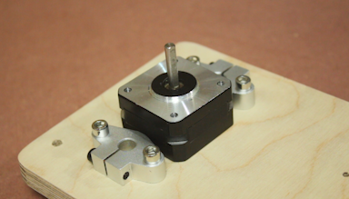
Then I bring 1 stepper motor we can call it Z axis stepper motor. The IR sensor and laser will be connected with this stepper motor, and this motor is responsible for the vertical motion of laser.
This motor increment 1 mm after 1 full rotation of turn table stepper motor.


Then I 3D printed case for the Z axis, I used two 8mm linear bearing and T nut for the assembly 8mm lead screw will pass from the centre of this part, as stepper motor moves it will lift up the whole assembly.
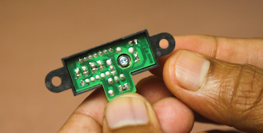

The I bring sharp IR sensor
The Sharp distance sensors are a popular choice for many projects that require accurate distance measurements. This IR sensor is more economical than sonar rangefinders,
yet it provides much better performance than other IR alternatives. Interfacing to most microcontrollers is straightforward: the single analog output can be connected to an analog-to-digital converter for taking distance measurements,
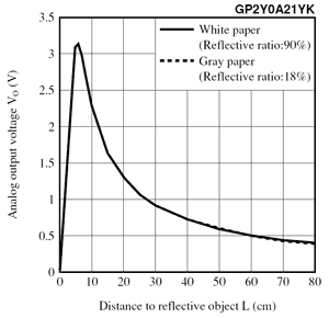
or the output can be connected to a comparator for threshold detection. The detection range of this version is approximately 10 cm to 80 cm (4″ to 32″).
The GP2Y0A21 uses a 3-pin JST PH connector that works with our 3-pin JST PH cables for Sharp distance sensors (not included),
as shown in the upper picture on the right. These cables have 3-pin JST connectors on one end and are available with pre-crimped male pins, pre-crimped female pins, and with unterminated wires on the other end. It is also possible to solder three wires to the sensor where the connector pins are mounted (see the lower picture to the right). When looking at the back, the three connections from left to right are power,
ground, and the output signal.
