 sandy
sandyHow-to-build-433mhz-RF-transmitter

An RF Beacon is a circuit that produces a continuous pulse that helps with tracking down an item or vehicle. One use for such a beacon would be to locate a rocket when it comes back down too far away to be seen. In this DIY Hacking project,
we will use a 433 MHz RF transmitter and a pair of 555 astable oscillators to create an RF beacon.
Component Required

1KΩ Resistor (R5, R6, R7) 10KΩ Resistor (R1, R3, R4, R8) 100KΩ Resistor (R2) 10nF Capacitor (C2, C3, C4) 10uF Capacitor (C1) 2N3904 (Q1, Q2) 555 Timer (IC1, IC2) RF Module (433 MHz)
RF Beacon Circuit Schematic

How Does it Work?
The RF beacon consists of three main units; A low frequency 555 oscillator, an audio (high frequency) oscillator, and an RF 433MHz module. The first unit, a low-frequency oscillator, creates a pulse at a frequency of approximately 1Hz which has an extremely large duty cycle (close to 99.9%).
This signal is then inverted thanks to Q1 in the form of a NOT gate, this creates a pulse with a duty cycle near 0.01%. The low duty cycle pulse is connected to the RESET of an audio 555 oscillator. When the output from the low-frequency oscillator stage (after Q1) becomes 0V, the audio oscillator (IC2),
is disabled and the result is no audio signal being produced. When the output of the low-frequency oscillator becomes VCC then the audio oscillator (IC2) is enabled and produces an audio able tone. This signal is inverted and then fed into the RF module which emits a tone on the 433MHz spectrum which can easily be picked up by receivers.
Constructing Your RF Beacon
The circuit can be built using through hole techniques including PCB, solderless breadboard, stripboard, and even matrix board. While the circuit shown here is rather large, it can easily be shrunk down using surface mount components.
That way, the circuit can easily be fitted onto small drones and RC planes while also keeping weight down to add RF tracking capabilities. For this project, a custom PCB has been designed to demonstrate the circuit using CNC milling.
All the files needed for this project can be found here including the CNC code needed to make the PCB: RF Beacon Project Files.
The Idea I get from https://maker.pro/pcb/projects/rf-beacon-build-433-mhz-rf-transmitter
then I Decide to make it'S PCB version also and share with you guys, so you can find the PCB files below
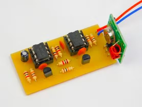
Custom PCB for RF Beacon Circuit


You can download and modify the PCB by visiting the link below https://oshwlab.com/sharmaz747/rf-bacon
If you seriously need quality PCB quickly in your hand then you must have to try JLCPCB PCB manufacturing service. They have Special offer of $2 for 1-4 Layer PCBs, free SMT assembly monthly. If new user signup today from this link JLCPCB.com you will get welcome coupons from JLCPCB.


SMT Assembly service of JLCPCB.com is cherry on top now get your PCB fully assembled and save your time and money Select components for your PCB from there Parts Library of 200k+ in-stock components they are offering $30 valued New User coupons & $24 SMT coupons every month $8.00 setup fee, and $0.0017 per joint
Now no need to order components separately for you PCB and get free from stress of soldering them on PCB just try PCB SMT assembly service and get you PCB with components pre assembled and ready for the project
👉 Try PCBA service of JLCPCB.com and save your time and money, get PCB ready for project, 200K+ components in library of JLCPCB.com as well as 3rd party parts to choose from. Assembly will support 10M+ parts from Digikey, mouser
👉 $30 valued New User coupons
👉 $24 SMT coupons every month
- Follow the simple step to get this PCB board.
1 - Download the circuit board Gerber file: https://oshwlab.com/sharmaz747/rf-bacon
2 - Create an account using the link below: JLCPCB.com
3 - visit JLCPCB.com Add the Gerber file...
Read more »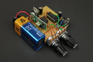
 Mrinnovative
 selena1995
 STAR
STAR
 mbsg99