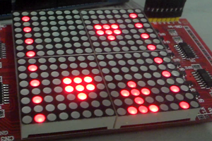
I followed this Instructables article for the most part. https://www.instructables.com/Led-Cube-8x8x8/
The interesting thing is the Arduino does not have enough pins to drive each LED individually. What this does is light up each of the 8 planes separately. Like the old tube TVs, the refresh rate is so fast that the eye cannot tell this is going on. When debugging the software it helps to pause the refresh portion of the software so you can see each plane light up.
To accomplish this with an Arduino, there are eight 8-bit registers and a demultiplexer. An entire plane's worth of data is latched into the registers and then that plane is lit up for a very brief period of time. The next planes data is then latched and that is lit up. This continues in a tight loop. The LEDs do not fade appreciably before the next cycle. It should be noted that this effectively works like PWM in that the LEDs are operating at a 1/8 duty cycle so the resistors need to be sized accordingly.
I won't go into great detail other than to say I used an Arduino instead of an ATmega32 microcontroller chip as this article shows.
The heart of the logic is an 8 x 8 byte matrix. Each bit represents an LED. The main loop chugs along, modifying this matrix periodically. In the background is an ISR that is reading the matrix and updating the LEDs at a very fast rate.
I have included some code for the Arduino that drives this setup.

 Aron Bordin
 Robert Mordzon
