 Catch a Soldering Iron
Made from a couple of old IR remote controls, to recharge 'other' remote control batteries. I tried to aim for a novel entry, which does something slightly 'useful'. And of course it runs off USB power.
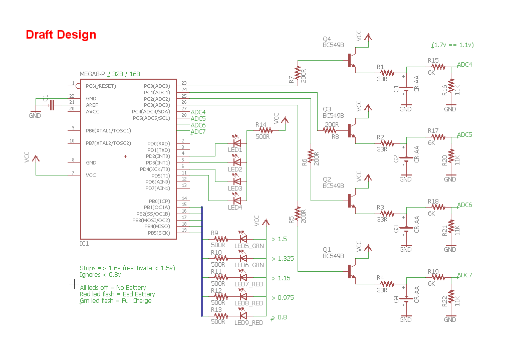
Using the standard Amtel Studio 6, the compiled code is under 900 bytes. And the attached source contains the binary I used.
.
This long video explains the setup, construction and some testing...
.
I quick call out to the best line in the code:
sleep_mode();
without "you", I would have to add more components.


 Insapio Limited Company
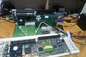
 Lydian
 Neal
Neal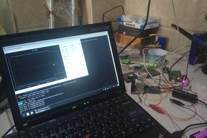
a battery destroyer that gives up to "800% more life"? wtf?