 lion mclionhead
The lion kingdom uses the cheaper commlite adapter.
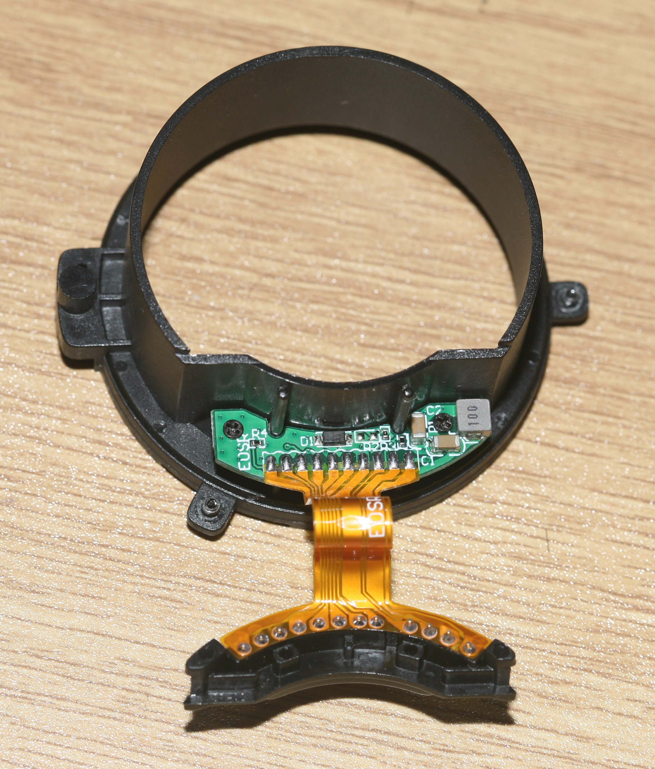
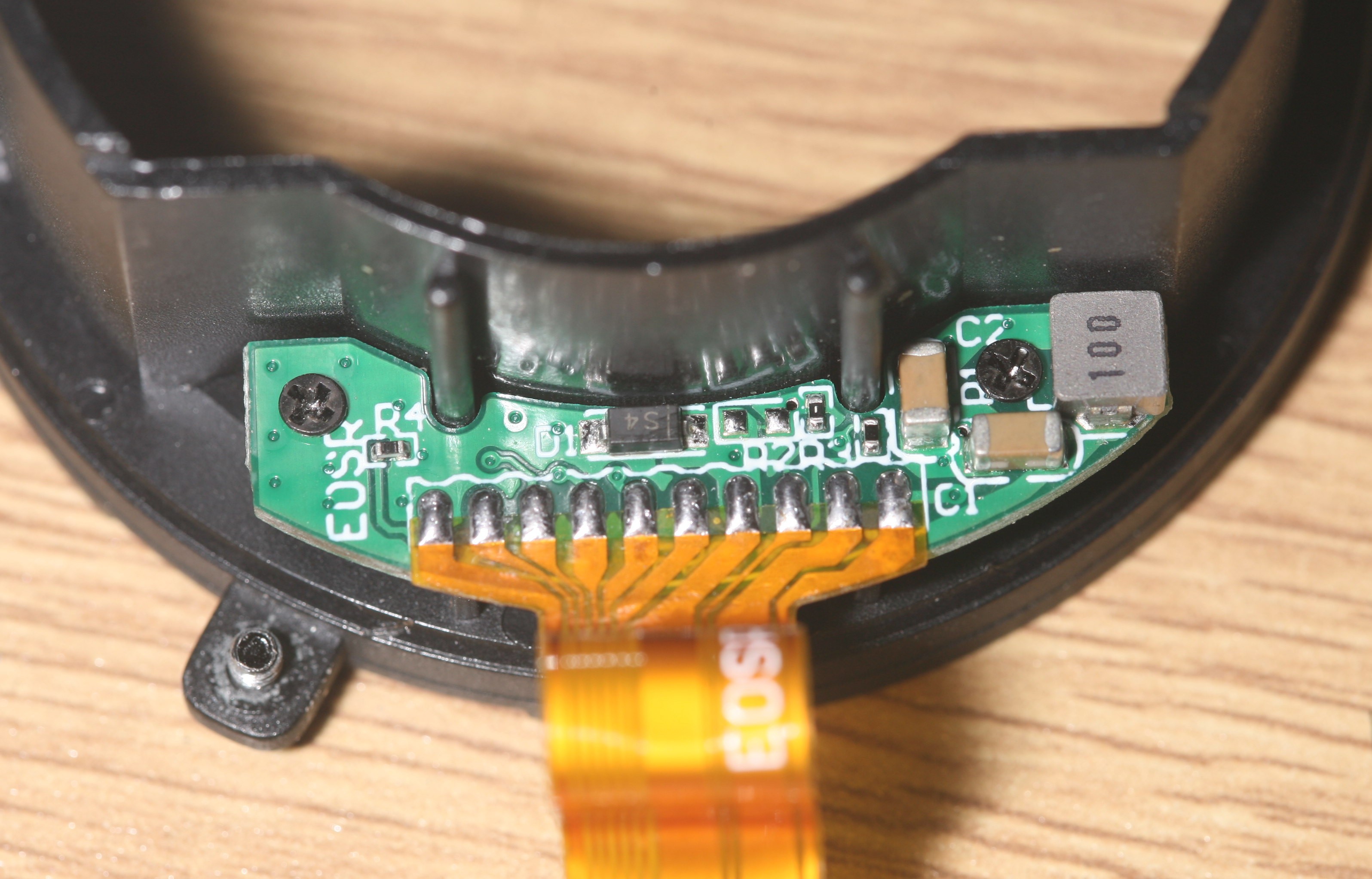
It has some passive components. There's a tank circuit & shottky diode connecting the logic ground to the battery ground. There's a 1k pullup resistor R3 generating the lens detect signal. R4 is 22k. R2 is 500R. Everything was intact. There was hard water staining around the pins facing the camera but nowhere else. The camera was untouched.
There is a low effort, incomplete teardown on
https://kolarivision.com/the-canon-eos-rp-disassembly-and-teardown/
The mane idea is it's not designed to be serviceable as all the adhesive rubber sections have to be removed, but he didn't document all the screw locations. Once inside, there are no panels which have to be desoldered or hidden ribbon cables. He didn't document any of the lens mount or anything in high enough resolution to figure out pinouts.
The EF protocol was reverse engineered here:
https://gist.github.com/marcan/858c242db2fc595da1e0bb70a05192fc
There is a clearer description of the signals here:
https://web.media.mit.edu/~bandy/invariant/move_lens.pdf
The lion kingdom once dreamed of manually controlling an EF lens & making a video camera. It took 20 years for someone to finally reverse engineer the EF protocol & 3D printing finally makes it possible to mount an EF lens on a custom sensor. Unfortunately, all modern cameras already have video.
The RF lens protocol has never been reverse engineered but is believed to use DRM. The lion kingdom determined the 5 SPI signals of the EF to be passed through the RF pinout, along with a strange pulse waveform. The DET pin comes from some combination of SPI pins.
Having 2 working EF cameras allowed good signals to be compared to the dead EOS RP signals.
A series of voltage tests convinced the lion kingdom that the RP body was damaged & not the lens adapter. With no lens attached, DET & MOSI had a strange pulse waveform, MISO had 3V, CLK had 0. With the lens attached, MOSI had 0, MISO had 5V & CLK stayed 0. Water was on the lens adapter but not the body, so it was probably damaged by a short circuit.
There's no pulse waveform on the good cameras. With no lens attached, MISO has 5V, MOSI has 0V, DET has 5V. When a lens is attached, CLK sends a bunch of 8 bit bursts & gives up.
It was surprising that the RP has no protection for the lens pins.
Discussions
Become a Hackaday.io Member
Create an account to leave a comment. Already have an account? Log In.