 Gregor
Many large, industrial scale 3D-printers that cost several tens of thousands of Dollars (or Euro's) not very long ago (about the same time RepRap, Makerbot, Ultimaker et al. became popular) are being decommissioned for trivial problems. Some have software errors, some have clogged extruders. Some ran out of filament. Many get dumped because their owners make a cost/benefit calculation, and with the annual retainer for a service contract being about the cost of a RepRap descendant, that calculation quickly tips into the "time to write-off" side.
These are also complex machines with many sensors, actuators and several layers of software all working together. This makes them error-prone, and, being closed-source (and maintenance literature hard to find), hard to repair.
Thus, they can be picked up for a snap (in monetary terms, being bulky they carry a lot of mass). My particular unit booted, initialized, calibrated and even printed the first layers, but would intermittently stop with the error code "14, 129", which the service manual for another printer of the same line (probably running the same software) indicates as an extruder problem: "Toggle Head failure".
While taking apart the extruder head, I noticed a small PCB (outlined orange in one of the photos) with two IR reflection sensors (QRE1113 or equivalent) on the back. They shine their light on a black and silver metallic sticker which is on the rod that moves the extruders into and out of the way.
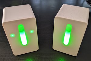
Because the white LED's of the interior lighting had failed (probably due to prolonged activation in an environment of 70 degrees Celcius), I thought the same must have happened to the IR LED. Swap out the sensors for fresh ones (an easy SMT repair job), reassemble the machine (not so easy) and do a test run: no more problems!
Other common errors on Dimension machines:
- the wiring on the extruder servo motor encoder fails due to shaking and thermal exposure
- bubbling support / build materials (and because of that clogged/blocked extruders, etc.) indicate
- empty backup battery coin cell on motherboard corrupts memory of installed cartridges (which manifests as weird "Shutting down - Continue"-errors while initializing)
- When these work they're wonderful (true tolerance, real ABS prints with soluble support and zero warping!) but my god are they error-prone
Hopefully, this saves other machines from landfill!
 Stefan Lochbrunner
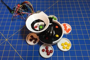
 Nathan Peterson
 Ben Brooks
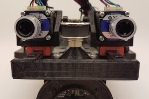
 Fabian
outstanding