 JP Gleyzes
A long time ago I made a first HDD clock. This video became very fast "viral" not because of the clock itself but because of the noise this clock made... (Today almost 500k views !)
It was a lot of fun but really this clock was totally unusable...
Here it is, you can laugh if you crank up the volume !
I could have stopped here my investigations with Hard Disks Drives but I wanted something quieter (even noiseless) and which could stay in my home without being immediately destroyed by my wife... So something "almost pretty".
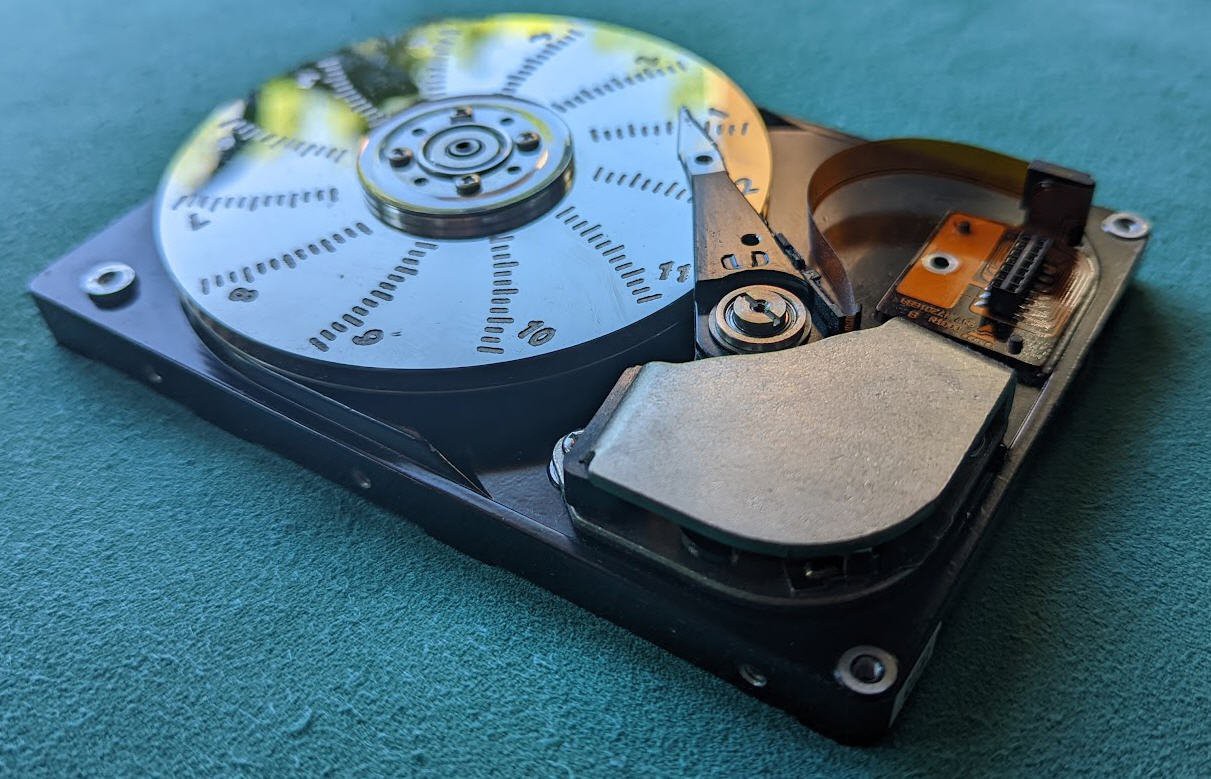
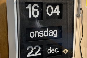
The result is this analog + digital clock that I made from another hard disk
My first attempt was this one :
All the inner parts of the drive look like untouched, the arm is fully moving and displays the minutes for each hour. The disk is rotating just every "full" hours.
The motion is smooth and somewhat adictive.
Here is the first video of the clock : we were ten years ago and it was 10:30 am
Now let's see how all this works and how you can do your own "HDD clock".
This project was published on my Website ten years ago, but I will now publish the whole design, the source code, everything in open source and open hardware.
And, If I am not too lazy, I will as well try to port it on an ESP32 MCU and design an android App to get rid of the PC App which is a bit outdated today!
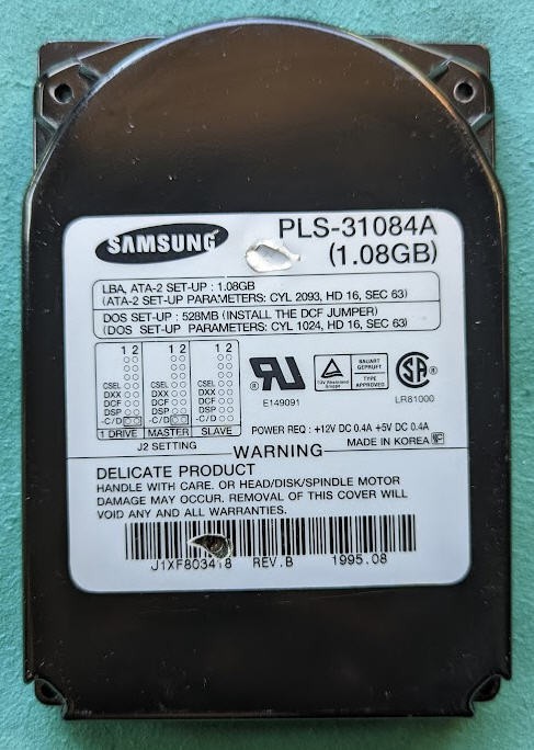
choosing the right disk
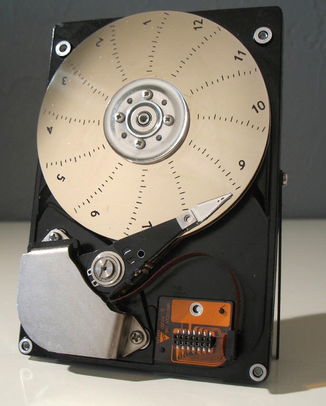
Let's start by choosing the right disk model. Almost any HDD will work but one important thing is mandatory : you must have at least two platters into the disk. We will see why later !
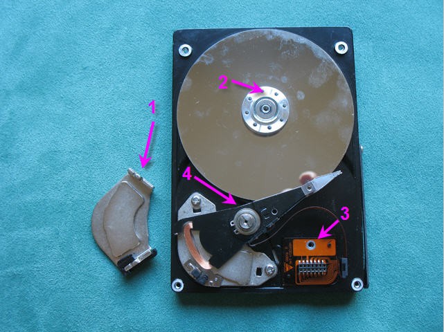
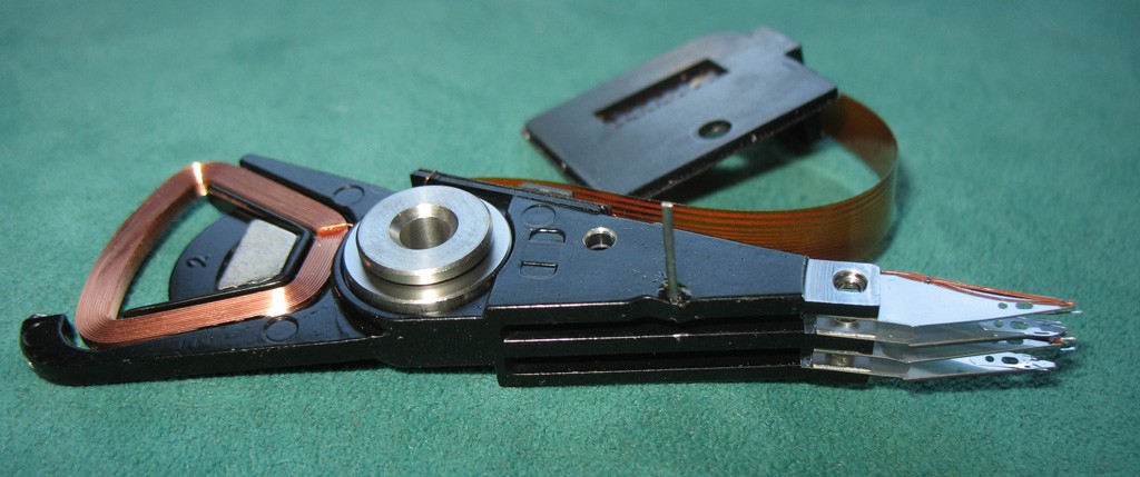
A Hard disk drive is, by itself, a nice "piece of art". It's a precise mechanism with a shining almost perfect mirror.
I decided to keep as much as possible of the original HDD to convert it into a working clock.
My specifications were as follows :
- as little visible modifications on the disk
- the head arm should indicate the minutes
- the rotating disk should indicate the hours
- the device should be automatic on startup
- the disk should be powered by any 5V coming either from a USB charger or directly from a PC USB host
- a USB interface should provide access to a software to tune and setup the device (plug & play)
- Time should be kept in case of a power failure
- clock should be noiseless
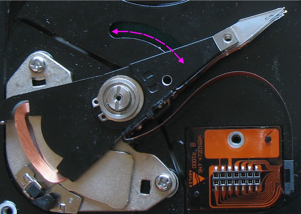
Modifying the heads arm
Wikipedia tells us that a moving-coil galvanometer is a type of ammeter: an instrument for detecting and measuring electric current. It is an analog electromechanical transducer that produces a rotary deflection of some type of pointer in response to electric current flowing through its coil in a magnetic field.
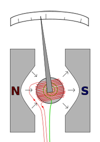 The D'Arsonval/Weston galvanometer used today is constructed with a small pivoting coil of wire in the field of a permanent magnet. The coil is attached to a thin pointer that traverses a calibrated scale. A tiny torsion spring pulls the coil and pointer to the zero position. When a direct current (DC) flows through the coil, the coil generates a magnetic field. This field acts against the permanent magnet. The coil twists, pushing against the spring, and moves the pointer. The hand points at a scale indicating the electric current
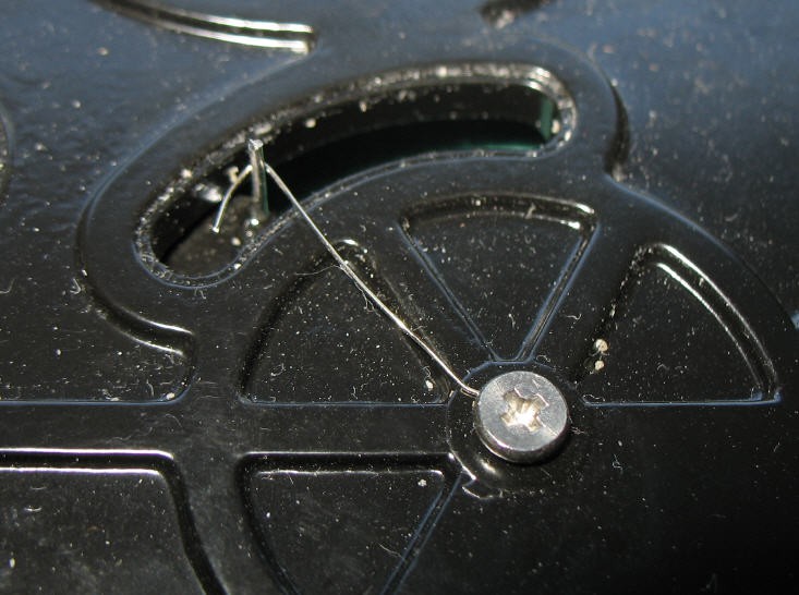
Our HDD heads arm is almost a galvanometer but it must be equiped with a litlle torsion spring to convert it into a DIY moving-coil galvanometer.
When I said that this clock would be "analog and digital" I wasn't lying at all... this galvanometer is fully analog. And we will see that the rest of the clock is much more digital!
Adding a position sensor
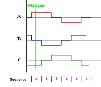
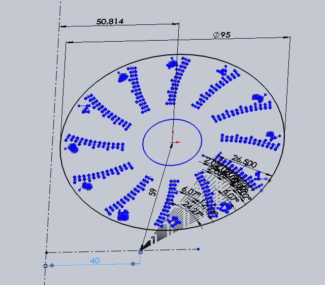
When the disk rotates you don't know what is its position. As we will engrave the platter with hours marks, we need to have a way to know "where is noon".
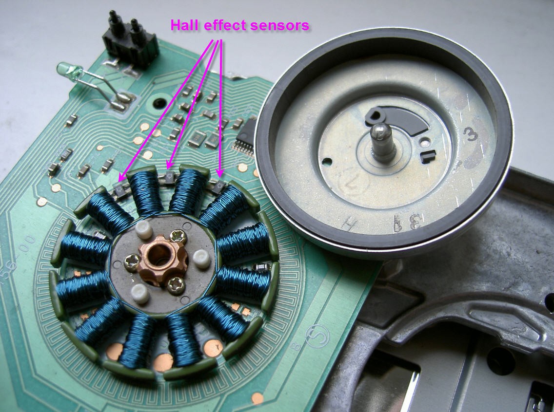
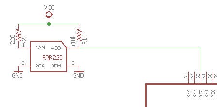
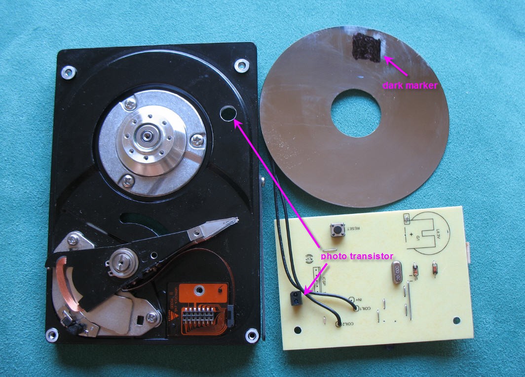
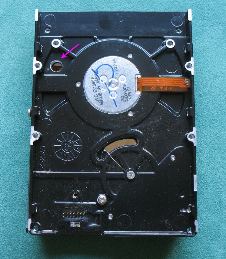
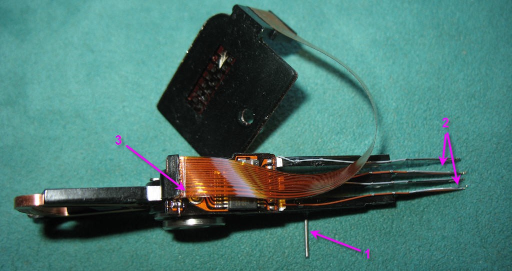
A RPR220 phototransistor is soldered on the PCB (details will come) and its led focusses IR beam on the bottom platter of the disk. A hole is drilled in the disk enclosure for that. A dark spot is painted on the disk to be detected easily by the sensor.

On the left side picture you can see half...
Read more »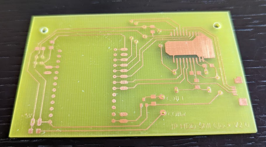


 iSax
iSax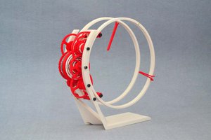
 ekaggrat singh kalsi
 Jac Goudsmit
Thanks.
Right but you don't know where is located the upper platter... So it will remain a manual process.
And the time is not stable
as the speed may vary.
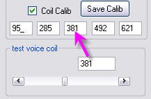
Finally this "calibration" is not that complicate!
(4 screws to tighten !).