 Splendide_Mendax
-
1Introduction
![]()
This project was fascinated and inspired by AWTRIX (AWsome maTRIX) project.
A maker from German created a full-color dot matrix that displays applications from simple time display to Fortnite account statistics. I have noticed that the matrix (32 × 8 WS2812B LEDs) is driven by the ESP8266 WLAN microcontroller. Therefore, I would like to "fork" this project using AMB23 or BW16 (RTL8722DM/RTL8720DN) which supports WS2812B LED drivers.
-
2Mapping linear LEDs into a Matrix
![]()
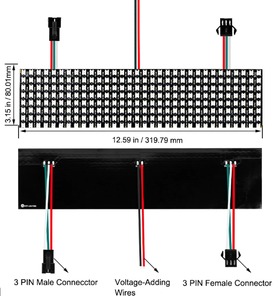
Upon getting a Digital Flexible WS2812B LED Matrix, we first need to understand the direction of how the LEDs are chained together. Upon running some demo examples, the direction of the LED lights up of my hardware is shown below:
- starting position is at TOP LEFT
- the direction of LED chains is ZIG ZAG in the order from TOP to DOWN
![]()
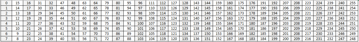
If we assign the index of the starting LED to be "0", the sequence of the whole LED matrix can be mapped into a table like this:
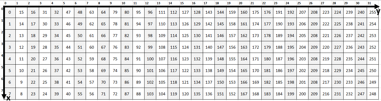
However, it is still inconvenient for the user to locate any of the 255 LEDs on board. We want to add a coordination system on top of the table so that users only need to input the X-axis and Y-axis in the code, to locate and turn on the corresponding LED. Therefore, I created a coordination system as shown below, the horizontal direction is assigned as Y-axis (from 0 to 31), and the verticle direction is assigned as X-axis (from 0-7).
Now, the problem we are facing is converting from linear values to (x, y) coordinates on this X-Y coordination system with some simple maths.
With default settings: NUM OF ROWS = 8, NUM OF COLS = 32, and any given (x , y) coordinates.
- FOR THE EVEN COLUMNS
- LED Location = x + y * NUM OF ROWS
- for example, input (1, 2) will result in 1 + 2 * 8 = 17
- LED Location = x + y * NUM OF ROWS
- FOR THE ODD COLUMNS
- LED Location = (NUM OF ROWS - 1) - x + y * NUM OF ROWS
- for example, input (5, 29) will result in 7 - 5 + 29 * 8 = 234
- LED Location = (NUM OF ROWS - 1) - x + y * NUM OF ROWS
Now, we successfully assigned all LEDs on this matrix with a unique (x, y) coordination.
REFERENCES
[1] How to use Excel to Animate LEDs! Arduino + WS2812 LEDs
[2] Useful Tool: LED Matrix Editor
================================ FUNCTION TEST ================================
In order to test the function mapLEDXY() that converts linear LED index value to (x, y) coordinates,
void mapLEDXY(int y, int x, byte RED, byte GREEN, byte BLUE)
I have converted some simple patterns from the reference link attached above. And use some simple functions to display it.
void symbol1()
{
  // <=
  mapLEDXY(0, 3, 39, 174, 232);
  mapLEDXY(1, 2, 39, 174, 232);
  mapLEDXY(1, 3, 39, 174, 232);
  mapLEDXY(1, 4, 39, 174, 232);
  mapLEDXY(2, 1, 39, 174, 232);
  mapLEDXY(2, 2, 39, 174, 232);
  mapLEDXY(2, 3, 39, 174, 232);
  mapLEDXY(2, 4, 39, 174, 232);
  mapLEDXY(2, 5, 39, 174, 232);
  mapLEDXY(3, 0, 39, 174, 232);
  mapLEDXY(3, 1, 39, 174, 232);
  mapLEDXY(3, 2, 39, 174, 232);
  mapLEDXY(3, 3, 39, 174, 232);
  mapLEDXY(3, 4, 39, 174, 232);
  mapLEDXY(3, 5, 39, 174, 232);
  mapLEDXY(3, 6, 39, 174, 232);
  mapLEDXY(4, 2, 39, 174, 232);
  mapLEDXY(4, 3, 39, 174, 232);
  mapLEDXY(4, 4, 39, 174, 232);
  mapLEDXY(5, 2, 39, 174, 232);
  mapLEDXY(5, 3, 39, 174, 232);
  mapLEDXY(5, 4, 39, 174, 232);
  mapLEDXY(6, 2, 39, 174, 232);
  mapLEDXY(6, 3, 39, 174, 232);
  mapLEDXY(6, 4, 39, 174, 232);
  mapLEDXY(7, 2, 39, 174, 232);
  mapLEDXY(7, 3, 39, 174, 232);
  mapLEDXY(7, 4, 39, 174, 232);
}
void symbol2(int shift, byte RED, byte GREEN, byte BLUE)
{
  // .:iL
  mapLEDXY(0 + shift, 6, RED, GREEN, BLUE);
  mapLEDXY(2 + shift, 5, RED, GREEN, BLUE);
  mapLEDXY(2 + shift, 6, RED, GREEN, BLUE);
  mapLEDXY(4 + shift, 3, RED, GREEN, BLUE);
  mapLEDXY(4 + shift, 4, RED, GREEN, BLUE);
  mapLEDXY(4 + shift, 5, RED, GREEN, BLUE);
  mapLEDXY(4 + shift, 6, RED, GREEN, BLUE);
  mapLEDXY(6 + shift, 1, RED, GREEN, BLUE);
  mapLEDXY(6 + shift, 2, RED, GREEN, BLUE);
  mapLEDXY(6 + shift, 3, RED, GREEN, BLUE);
  mapLEDXY(6 + shift, 4, RED, GREEN, BLUE);
  mapLEDXY(6 + shift, 5, RED, GREEN, BLUE);
  mapLEDXY(6 + shift, 6, RED, GREEN, BLUE);
}


// --------------------------------------------
// map from (x, y) to LED location in strip
// zig zag
// top left LED starting bit
// --------------------------------------------
void mapLEDXY(int y, int x, byte RED, byte GREEN, byte BLUE)
{
  int RGBlocation = 0;

  if (y % 2 == 0)
  { // even column
    RGBlocation = x + y * NUM_OF_ROWS;
  }
  else
  { // odd column
    RGBlocation = 7 - x + y * NUM_OF_ROWS;
  }

  led.setPixelColor(RGBlocation, RED, GREEN, BLUE);
}

void setup()
{
  led.begin();
  led.clear();
  // Set a specific LED with a certain color
  //  led.setPixelColor(0, 50, 0, 0);
  //  led.setPixelColor(1, 0, 50, 0);
  //  led.setPixelColor(2, 0, 0, 50);
  //  led.setPixelColor(8, 0, 0, 50);
  //  led.show();
  //  delay(1000);

  // Fill the entire LED strip with the same color
  //  led.fill(60, 0, 25, 0, 8);
  //  led.show();

  symbol1();
  led.show();
  delay(1000);
  symbol2(8, 0, 153, 76);
  led.show();
  delay(1000);
  symbol3(16, 255, 128, 0);
  led.show();
  delay(1000);
  symbol4(24, 255, 204, 204);
  led.show();
  delay(1000);
  led.fill(0, 0, 0, 0, 255);
  led.show();

  // heart shape shifting
  for (int i = 0; i < 32; i = i + 2) {
    symbol3(i, 255, 153, 255);
    led.show();
    delay(100);
    led.clear();
    led.show();
  }
}
The display result is shown in the demo video:
-
3Display ASCII Symbols on Matrix
Next, based on the [2], we get ASCII patterns of digits, letters, signs, and other symbols. The state of the 8x8 matrix can be presented as an array of unsigned long integers (uint64_t). Besides, a primary example code is also provided on this website. We can modify it and try to display some of these ASCII patterns on the Matrix hardware.
================================ to be continued ===================
Ameba Neo Matrix
Create an "AWTRIX" Project based on Ameba RTL8722DM/RTL8720DN


Discussions
Become a Hackaday.io Member
Create an account to leave a comment. Already have an account? Log In.